Panel Cooling and Ventilation Design
Thermal management strategies for panel enclosures.
Panel Cooling and Ventilation Design
Thermal management is one of the most important parts of low-voltage panel design. In an IEC 61439 compliant assembly, cooling is not an optional accessory; it is part of the evidence that the switchboard will operate safely, maintain dielectric performance, and avoid premature ageing of components. Per IEC 61439-1 Clause 10.10, the assembly must be verified for temperature rise, either by test or by a validated calculation method such as IEC/TR 60890. In practice, this means the designer must understand power dissipation, ambient conditions, enclosure construction, airflow path, and any active cooling equipment before the panel is released for manufacture.
Good ventilation design balances three objectives: keep internal temperatures within the standard’s limits, preserve the assembly’s declared degree of protection, and maintain reliability over the full service life. As documented in the ABB and Hensel IEC 61439 application guides, this requires the panel builder to treat losses from busbars, protective devices, power supplies, drives, and auxiliary equipment as a system-level thermal load, not as isolated component values.
Thermal Requirements in IEC 61439
IEC 61439-1 sets clear thermal performance expectations for low-voltage switchgear and controlgear assemblies. The standard does not specify a single “safe temperature” for every part of the enclosure. Instead, it defines temperature-rise limits for the assembly, its terminals, external accessible parts, and certain internal conductors. These limits are intended to protect insulation, prevent contact hazards, and keep components within their rated operating range.
For indoor assemblies, the reference ambient conditions are typically an average ambient air temperature of 35°C over 24 hours, with a maximum of 40°C, a minimum of -5°C, altitude up to 2000 m, and relative humidity up to 90% at 20°C or 50% at 40°C. These service conditions are given in IEC 61439-1 and repeated in manufacturer guidance from ABB, Hensel, and Schneider Electric. If the actual installation exceeds these limits, the assembly must be derated or redesigned.
IEC 61439-1 temperature-rise limits commonly used in design include the following: internal air temperature rise around 24 K above ambient for the enclosure, terminals up to 70 K, bare copper busbars up to 105 K, and accessible external metal parts limited to 30 K where frequently touched. These values are essential when selecting vents, fan units, filters, heat exchangers, or air-conditioning systems. They also influence the layout of heat-generating devices so that hotspots do not create local temperature exceedances.
Thermal effects also interact with dielectric performance and insulation coordination. IEC 61439-1 addresses these issues in its verification requirements, and elevated temperature can reduce the durability of insulation materials, increase contact resistance, and accelerate ageing of electronic modules. In other words, temperature rise is both a compliance issue and a reliability issue.
Ambient Conditions and Installation Environment
Cooling design starts with the environment, not the enclosure. A panel installed in a clean, climate-controlled electrical room has very different thermal requirements from a switchboard exposed to solar load, dust, humidity, or repeated door opening. IEC 61439-1 assumes a defined indoor service environment unless the assembly is specifically intended for outdoor use.
For outdoor applications, the service conditions become more demanding. Commonly referenced ranges extend from -25°C to +40°C, and the assembly must be protected against rain, condensation, direct sunlight, and wind-driven dust. IEC 60529 degree-of-protection requirements become important here, and outdoor enclosures often require at least IPX1 drip protection as a minimum baseline, with much higher IP ratings used in real installations. Manufacturer documentation from ABB and Hensel also highlights the need for anti-condensation heaters, sunshields, and carefully designed vent paths in humid or exposed environments.
Altitude matters as well. Above 2000 m, reduced air density lowers cooling performance and reduces dielectric withstand margins. Where a panel is intended for high-altitude installation, the designer must apply the manufacturer’s correction factors or confirm the assembly by suitable test or calculation. This is especially important for densely packed systems with high losses from power electronics, busbars, or motor feeders.
How Heat Is Generated Inside the Panel
The internal heat load of a switchboard is the sum of all power losses generated by installed components. This includes busbar losses, circuit breaker losses, contactor coil dissipation, power supply heat, PLC and I/O module losses, drives, meters, communication devices, and any auxiliary transformer or UPS heat output. Schneider Electric and ABB both emphasize that the total loss must be declared for ventilation or air-conditioning sizing.
Losses are not constant across all operating states. Diversity factor, load factor, and duty cycle affect the real thermal profile. A feeder that carries 630 A on its nameplate does not necessarily dissipate its full worst-case loss continuously, but the thermal design must still assume the most severe credible combination of loading conditions. If the design underestimates these losses, the panel may still pass initial function tests but fail in service through nuisance trips, shortened component life, or insulation stress.
Power electronics create particular challenges. Variable speed drives, soft starters, UPS systems, and rectifiers can produce concentrated losses that cannot be managed only by general enclosure ventilation. These components may require segregated airflow paths, dedicated fans, or manufacturer-approved clearances to avoid recirculation of hot air.
Verification of Temperature Rise
IEC 61439-1 allows two principal verification routes for temperature rise: test and calculation. Clause 10.10 is the governing verification clause, and it is one of the most important compliance steps in a panel project.
Testing provides the strongest evidence because it measures the real assembled product under operating conditions. It is typically preferred for critical assemblies, unusual layouts, compact high-density panels, or when the loss distribution is difficult to model accurately. Calculation may be used when the enclosure, component arrangement, and losses fall within a validated framework, and IEC/TR 60890 is the recognized method for estimating temperature rise in enclosures with natural or forced ventilation.
IEC/TR 60890 considers enclosure dimensions, losses, airflow, thermal resistance, and venting arrangement. It is widely used in engineering tools supplied by manufacturers such as ABB and Hensel for early-stage sizing. However, calculation is only as reliable as the input data. If the heat losses are incomplete, the ambient assumptions are unrealistic, or the ventilation geometry changes during manufacturing, the calculated result may not represent the finished assembly.
For this reason, good practice is to use calculation for preliminary design and component selection, then confirm critical assemblies by test or by manufacturer-validated design rules. This approach reduces risk and helps ensure that the final assembly matches its thermal verification basis.
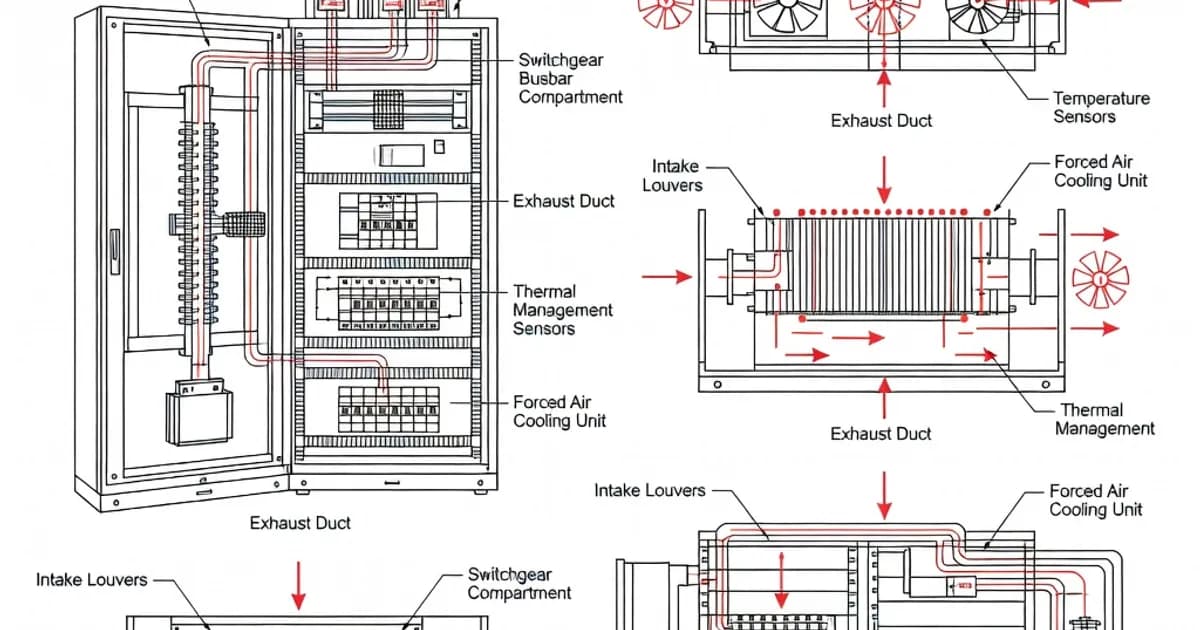
Cooling and Ventilation Methods
Panel cooling should follow a hierarchy of solutions. Start with passive thermal design, then add forced ventilation or heat exchange only when the internal losses require it. This minimizes cost, complexity, maintenance, and failure points.
Natural convection is the simplest method. Cool air enters through low-level vents, rises as it absorbs heat, and exits through high-level outlets. This works well for moderate losses, wide enclosures, and panels installed in cool ambient conditions. Natural ventilation is often sufficient for distribution boards with limited electronics, provided the airflow path is unobstructed and the ingress protection remains acceptable.
Forced-air ventilation adds fan units to increase airflow and improve heat removal. It is suitable when natural convection cannot maintain temperature-rise limits. Fan systems must be selected for the actual pressure drop through filters, grilles, and internal partitions. They also require maintenance planning because blocked filters reduce flow quickly and can cause a rapid rise in temperature. In dusty industrial settings, fan systems should be paired with appropriate filtration and cleaning schedules.
Air-air heat exchangers are used when the panel must remain sealed against the external environment but still needs improved thermal performance. They transfer heat without mixing internal and external air, which helps preserve IP protection in dirty or humid locations.
Air-conditioning units provide the highest cooling capacity and are used when internal losses are high, ambient temperatures are elevated, or precise thermal control is necessary. They are often justified in compact panels with large drive losses or in outdoor cabinets exposed to solar radiation. Their design must include condensate management, compressor reliability, and operating range validation.
Anti-condensation heaters are not cooling devices, but they are part of the thermal design in cold or humid environments. They prevent moisture accumulation when the panel cools below the dew point, especially during shutdown or night-time temperature drops. Hensel and ABB both note that outdoor or humid installations often need controlled venting and heating together, not as separate options.
Specification Table: Thermal Design Limits and Verification
| Item | Typical IEC 61439 Reference Value | Design Impact |
|---|---|---|
| Reference ambient for indoor assemblies | 35°C average over 24 h, max 40°C, min -5°C | Basis for thermal verification and derating |
| Relative humidity | 90% at 20°C or 50% at 40°C | Condensation risk and insulation protection |
| Altitude | Up to 2000 m | Cooling and dielectric correction may be required |
| Internal air temperature rise | Approximately 24 K | Main target for enclosure ventilation design |
| Terminals | 70 K | Prevents contact and insulation damage |
| Bare copper busbars | 105 K | Controls conductor ageing and mechanical stress |
| Accessible external metal parts | 30 K | Limits burn risk for frequently touched surfaces |
| Verification methods | Test per IEC 61439-1 Clause 10.10 or calculation per IEC/TR 60890 | Defines compliance pathway |
Design Principles for Effective Ventilation
Effective panel ventilation depends on airflow path design as much as on fan capacity. A powerful fan cannot compensate for recirculation, blocked outlets, or poor component layout. The designer should keep heat sources away from the top of the enclosure where possible, because warm air accumulates there. Sensitive electronics should not be placed directly above heavily loaded breakers, transformers, or busbar joints.
Internal separation plates can improve thermal control by forcing air to pass over the hottest zones rather than bypassing them. At the same time, partitions may increase pressure drop, so the ventilation calculation must reflect the final internal geometry. Cable entry should also be considered because dense cabling can obstruct air movement and trap heat near terminal areas.
External placement matters too. A cabinet mounted in direct sunlight may absorb far more heat than one installed in shade. In this case, a sunroof, reflective coating, or relocation under a canopy can significantly reduce cooling demand. For outdoor enclosures, the roof design should shed water efficiently while avoiding any obstruction to the intended ventilation openings.
Good practice also includes maintaining serviceability. Filters, fans, and cooling units should be accessible for cleaning and replacement without dismantling the whole assembly. If maintenance access is poor, real-world cooling performance often deteriorates long before the design assumptions expire.
Comparison of Cooling Approaches
| Cooling Method | Typical Use | Advantages | Limitations |
|---|---|---|---|
| Natural ventilation | Low to moderate losses, cool ambient, indoor panels | Simple, low cost, low maintenance | Limited heat removal, sensitive to ambient temperature |
| Forced-air ventilation | Moderate to high losses, controlled environments | Better heat transfer, scalable | Filter maintenance required, IP impact must be managed |
| Air-air heat exchanger | Dirty or humid locations where sealing must be preserved | Maintains enclosure separation from ambient air | Less effective than direct cooling, added cost |
| Air-conditioning | High-loss or outdoor enclosures, strict thermal control | Highest cooling capability, stable internal climate | Higher cost, condensate handling, compressor maintenance |
| Anti-condensation heating | Cold or humid installations | Reduces moisture risk during shutdown | Does not remove heat during operation |
Common Design Mistakes
One common mistake is to size cooling from the component catalogue alone without calculating the total internal loss. The enclosure, wiring, busbars, and auxiliary devices all contribute to the thermal load. Another error is to assume that an IP-rated cabinet is automatically thermally adequate. In reality, high IP ratings can restrict airflow and make heat removal more difficult, so the designer must explicitly account for that trade-off.
Another frequent problem is neglecting ambient derating. A panel that works well at 20°C can run too hot at 40°C, especially when exposed to solar gain or mounted in a poorly ventilated plant room. Designers also sometimes forget that door opening, maintenance procedures, and future equipment additions change the thermal balance over time. A panel should therefore be designed with enough thermal margin to accommodate foreseeable expansion.
Finally, cooling devices themselves are sometimes selected without considering failure modes. A fan that fails silently, a clogged filter, or a thermostatic controller set incorrectly can defeat the whole thermal design. For this reason, critical installations should include alarms, status contacts, or preventive maintenance checks for cooling equipment.
Best Practice for IEC 61439-Compliant Cooling Design
Start with the environment and define the actual service conditions. Confirm indoor or outdoor use, expected ambient range, humidity, altitude, solar exposure, and pollution level. Then calculate the total power loss of the assembly, including the worst credible operating condition. Use the loss data supplied by the original equipment manufacturers whenever possible, because ABB, Schneider Electric, and other manufacturers provide thermal data specifically intended for IEC 61439 design.
Next, choose the simplest cooling method that can maintain the required temperature rise limits. If natural ventilation is sufficient, avoid adding complexity. If not, progress to forced air, heat exchange, or air-conditioning based on verified thermal need rather than guesswork. Ensure the chosen method preserves the required ingress protection and complies with the assembly’s mechanical robustness requirements.
Where the design is critical, use testing to verify temperature rise under realistic loading. If calculation is used, follow IEC/TR 60890 carefully and validate all assumptions. For industrial applications, build in access for cleaning, inspection, and replacement of fans, filters, or cooling units. This is especially important in dusty, humid, or high-duty-cycle facilities where maintenance intervals strongly influence performance.
In short, thermal design should be treated as an engineering discipline, not an afterthought. A well-cooled panel is safer, more reliable, easier to maintain, and more likely to remain compliant throughout its service life.
References and Further Reading
ABB Workbook: The standard IEC 61439 in practice
ABB Technical Application Paper No. 11: IEC 61439 in practice
Hensel Guide: Design and assembly according to IEC/EN 61439
Overview of IEC 61439 low-voltage switchgear design
IEC 61439 switchgear engineering overview
Standards for further study: IEC 61439-1, IEC 61439-2, IEC/TR 60890, IEC 60529, and the applicable IEC 60947 component standards.
Frequently Asked Questions
Ready to Engineer Your Next Panel?
Our team of electrical engineers is ready to design, build, and deliver your custom panel solution — fully compliant with international standards.