Power Factor Correction Panel (APFC)
Automatic capacitor switching for reactive power compensation. Thyristor or contactor-switched, detuned or standard configurations.
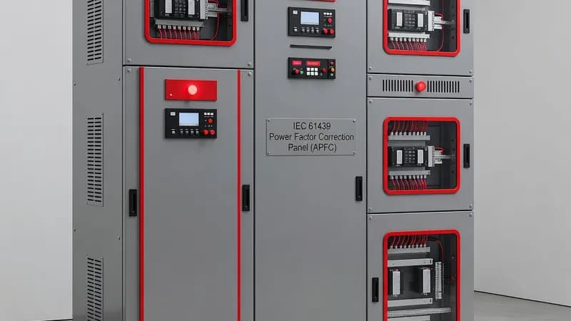
An Automatic Power Factor Correction Panel (APFC) is a low-voltage capacitor-switching assembly used to reduce reactive power demand, stabilize voltage, and improve electrical efficiency across commercial, industrial, and utility-connected installations. Built as an IEC 61439-1/2 verified assembly, an APFC panel typically integrates a microprocessor-based power factor controller, capacitor steps, switching devices, protection, metering, and ventilation within a coordinated enclosure system. Depending on the load profile, the panel may use AC contactors designed for capacitor duty per IEC 60947-4-1, or thyristor switching modules for fast, frequent step changes in installations with rapidly fluctuating loads such as VFD-driven process lines, elevators, welding equipment, or data center UPS systems. For harmonic-rich networks, detuned capacitor banks with series reactors are selected to avoid parallel resonance and to maintain capacitor life where THD levels are elevated; standard detuned designs commonly target 189 Hz or 210 Hz reactor tuning at 50 Hz systems. Typical APFC assemblies range from 50 kVAr to 2000 kVAr at 400 V or 690 V, with larger bank architectures built using stepped sections for 25, 50, 75, 100 kVAr or project-specific increments. The incomer is commonly protected by an MCCB or ACB with adequate breaking capacity, while each capacitor step may include HRC fuses, contactors, discharge resistors, and thermal monitoring. Where process continuity is critical, protection relays can supervise overload, unbalance, temperature, overvoltage, undercurrent, or harmonic abnormality. Metering power analyzers are frequently incorporated to log kW, kvar, PF, THD, demand, and harmonics for energy management and utility compliance. Mechanical and thermal design are central to reliable operation. APFC panels must accommodate heat dissipation from capacitors, reactors, and switching devices, often requiring forced ventilation, thermostatic fan control, or segregated compartments. Forms of internal separation such as Form 2, Form 3a, or Form 4 are selected based on maintenance philosophy, arc-flash mitigation expectations, and service continuity requirements. Enclosure design may also be coordinated to IP31, IP42, IP54, or higher depending on installation environment, while corrosive or dusty sites may require coated sheet steel or stainless steel enclosures. For industrial sites located in hazardous areas, design constraints can also intersect with IEC 60079 requirements for surrounding installations, and where arc containment is mandated, IEC 61641 testing principles may be referenced for internal arc effects in adjacent low-voltage equipment rooms. Compliance typically extends beyond IEC 61439 to IEC 60947 for switching and protection devices, IEC 61000 for electromagnetic compatibility, and IEC 60364-8-1 energy efficiency considerations in building systems. In export projects, UL 891 or CSA requirements may also be relevant for North American interfaces. Real-world applications include hospitals, where stable voltage supports imaging and HVAC loads; food and beverage plants, where compressors and pumps create inductive demand; wastewater facilities, where large motor populations operate intermittently; and renewable-energy sites, where APFC helps manage auxiliary load profiles. Properly engineered APFC panels deliver measurable reductions in demand charges, released transformer capacity, lower cable losses, and improved plant power factor without compromising network stability. Patrion APFC assemblies are engineered to match site harmonics, load variability, ambient temperature, and expansion requirements. The final design is typically coordinated with capacitor bank sizing, short-circuit withstand rating, ventilation strategy, and the upstream fault level so the complete IEC 61439 assembly can operate safely under real service conditions.
Components for This Panel
Capacitor Banks & Reactors selection, integration, and best practices for Power Factor Correction Panel (APFC) assemblies compliant with IEC 61439.
Contactors & Motor Starters selection, integration, and best practices for Power Factor Correction Panel (APFC) assemblies compliant with IEC 61439.
Moulded Case Circuit Breakers (MCCB) selection, integration, and best practices for Power Factor Correction Panel (APFC) assemblies compliant with IEC 61439.
Metering & Power Analyzers selection, integration, and best practices for Power Factor Correction Panel (APFC) assemblies compliant with IEC 61439.
Protection Relays selection, integration, and best practices for Power Factor Correction Panel (APFC) assemblies compliant with IEC 61439.
Applicable Standards
IEC 61439-2 (PSC) compliance requirements, testing procedures, and design considerations for Power Factor Correction Panel (APFC) assemblies.
EMC Compliance (IEC 61000) compliance requirements, testing procedures, and design considerations for Power Factor Correction Panel (APFC) assemblies.
IP Protection Ratings compliance requirements, testing procedures, and design considerations for Power Factor Correction Panel (APFC) assemblies.
UL 891 / CSA C22.2 compliance requirements, testing procedures, and design considerations for Power Factor Correction Panel (APFC) assemblies.
Industries Using This Panel
Power Factor Correction Panel (APFC) assemblies engineered for Commercial Buildings applications, addressing industry-specific requirements and compliance standards.
Power Factor Correction Panel (APFC) assemblies engineered for Industrial Manufacturing applications, addressing industry-specific requirements and compliance standards.
Power Factor Correction Panel (APFC) assemblies engineered for Data Centers applications, addressing industry-specific requirements and compliance standards.
Power Factor Correction Panel (APFC) assemblies engineered for Healthcare & Hospitals applications, addressing industry-specific requirements and compliance standards.
Power Factor Correction Panel (APFC) assemblies engineered for Water & Wastewater applications, addressing industry-specific requirements and compliance standards.
Power Factor Correction Panel (APFC) assemblies engineered for Renewable Energy applications, addressing industry-specific requirements and compliance standards.
Power Factor Correction Panel (APFC) assemblies engineered for Food & Beverage applications, addressing industry-specific requirements and compliance standards.
Power Factor Correction Panel (APFC) assemblies engineered for Pharmaceuticals applications, addressing industry-specific requirements and compliance standards.
Related Knowledge Articles
Designing and sizing APFC panels for optimal reactive power compensation.
Sizing power factor correction equipment for LV installations.
Comprehensive overview of all IEC 61439 parts, their scope, and how they apply to different panel types.
Methods for verifying panel temperature limits.
Frequently Asked Questions
Ready to Engineer Your Next Panel?
Our team of electrical engineers is ready to design, build, and deliver your custom panel solution — fully compliant with international standards.