IEC 61439 vs IEC 60439: What Changed and Why
Detailed comparison of the old and new panel assembly standards.
IEC 61439 vs IEC 60439: What Changed and Why
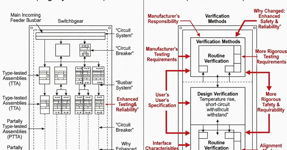
IEC 61439 replaced IEC 60439 to modernize the rules for low-voltage switchgear and controlgear assemblies and to remove long-standing ambiguity about who is responsible for safety, performance, and verification. The transition began in 2009 and became fully effective by 2014, with IEC 61439 now governing assemblies up to 1000 V AC and 1500 V DC. The most important shift was conceptual: instead of relying on the older TTA/PTTA model, IEC 61439 introduced the idea of a verified assembly, supported by explicit design verification methods and clearly assigned responsibilities for the original manufacturer, the assembly manufacturer, and the specifier. As documented in Schneider Electric’s explanation of the standard changes, this was intended to improve consistency, reduce disputes, and make compliance easier to demonstrate in real projects.
IEC 60439 had served industry for decades, but it left too much room for interpretation. Two assemblies could be described as compliant while having very different construction details, test histories, or thermal margins. IEC 61439 addresses that gap by requiring evidence that the assembly design and the final build both satisfy the standard’s verification criteria. In practice, that means better documentation, more predictable performance, and safer assemblies across a wider range of configurations, including modular and custom-built systems. Per IEC 61439-1, Clauses 10 through 13 now define the verification framework in a structured way rather than depending primarily on type-test labels.
What IEC 61439 changed at a glance
The new standard did not merely rename the old one. It changed how compliance is proven, how temperature rise is assessed, how short-circuit withstand is verified, and how conductor arrangements are limited. It also formalized the division of responsibility across the supply chain. The original manufacturer defines and verifies the design system; the assembly manufacturer builds the actual panel and completes the final verification steps; the specifier defines the operating conditions and performance requirements. Hager and Legrand both emphasize that this role split is one of the most important practical benefits of the standard because it reduces uncertainty from specification through installation.
| Aspect | IEC 60439 | IEC 61439 | Practical impact |
|---|---|---|---|
| Verification model | TTA and PTTA | Verified assembly using test, comparison with a reference design, or calculation | More flexible, but with clearer proof requirements |
| Responsibility | Less clearly divided | Original manufacturer, assembly manufacturer, specifier each have defined duties | Reduces contractual ambiguity |
| Temperature rise | Test-based approach with less explicit calculation guidance | Detailed verification requirements, including calculation methods for assemblies up to 1600 A | Better thermal design discipline |
| Short-circuit withstand | Required, but often interpreted through legacy testing practice | Explicit verification of withstand at prospective fault current | Improved consistency for fault-rated assemblies |
| Non-protected conductors | Less explicit | Restricted, with a total length limit of 3 m and defined arrangements | Lower risk of unprotected fault paths |
| Documentation | Often manufacturer-specific | Standardized verification record expectations | Easier handover and audit trail |
Why the standard was rewritten
The main reason for the IEC 60439-to-61439 transition was that the old framework no longer matched the complexity of modern low-voltage systems. Assemblies had become more modular, more customized, and more heavily integrated with electronics, monitoring, and automation. Under IEC 60439, the distinction between type-tested assemblies and partially type-tested assemblies was useful, but it was also rigid and sometimes misleading. An assembly could be built from tested parts and still perform poorly if the final arrangement changed airflow, conductor routing, or fault paths.
IEC 61439 replaces that static logic with a verification framework tied to the actual design. The standard recognizes that safety is not guaranteed by a label alone; it must be demonstrated for the complete assembly, including busbars, terminals, enclosures, functional units, and protective devices. The standard also aligns better with international procurement because it separates design intent from final manufacture. Schneider Electric notes that these changes were made to clarify roles and improve the reliability of published specifications across markets.
From TTA/PTTA to verified assemblies
Under IEC 60439, assemblies were commonly classified as type-tested assemblies or partially type-tested assemblies. This model depended heavily on a list of type tests, but it did not always tell the full story of how a custom assembly would behave in service. IEC 61439 replaces that with the concept of a verified assembly. Verification can be achieved by:
- testing the actual assembly or a representative design,
- comparing the design against a verified reference design, or
- using calculation or rules-based assessment where permitted by the standard.
Per IEC 61439-1 Clauses 10 to 13, the design verification process must cover key characteristics such as temperature rise, dielectric properties, short-circuit withstand, protection against electric shock, clearances and creepage distances, mechanical operation, and degree of protection. This is a major advance over IEC 60439 because it acknowledges that safety depends on the total design, not just isolated laboratory tests. ABB’s practical guidance on IEC 61439 shows how manufacturers now use design rules, verified reference configurations, and documentation packs to prove conformity efficiently without repeating unnecessary full tests for every variation.
Verification methods and clause structure
IEC 61439-1 makes verification more structured than IEC 60439 ever did. It requires evidence for each relevant characteristic, and it allows different methods depending on the characteristic and the assembly design. For temperature rise, for example, calculation methods are permitted for assemblies up to 1600 A under the standard’s rules. For other characteristics, testing or comparison with a verified reference design may be more appropriate. The result is a more engineering-driven approach to compliance.
Per IEC 61439-1 Clause 10.11, temperature-rise verification is central to the new regime. Clause 10.9 addresses dielectric withstand, while Clause 10.8 covers protection against electric shock and integrity of the enclosure system. Clause 10.10 addresses short-circuit withstand, and Clause 10.12 deals with the resistance of materials and components to abnormal heat and fire. IEC TR 61439-0:2022 further clarifies common country practices and gives useful guidance on maintenance and application, which is especially helpful for multinational projects.
Temperature rise: more explicit, more demanding
Temperature rise is one of the most important differences between the two standards. IEC 61439 tightens the engineering logic by requiring a verified thermal design rather than relying on general assumptions. In practice, the standard limits the temperature rise of terminals and external accessible surfaces and requires assemblies to be verified at the specified ambient conditions, commonly based on an average ambient of 35°C during testing. The research summary notes practical limits such as 70 K for terminals and 105 K for external parts, depending on material and accessibility conditions, with verified methods required to show compliance.
This is especially relevant for dense designs, high-current busbar systems, and modular distribution boards. Thermal performance can change significantly when cable bundles, device spacing, or enclosure ventilation changes. That is why IEC 61439 gives such importance to the original manufacturer’s design system. In other words, a panel builder cannot assume that a passed test on one layout automatically validates all other layouts. The thermal behavior must be verified for the actual arrangement or for a truly equivalent reference design.
Short-circuit withstand and conductor limits
IEC 61439 also strengthens short-circuit expectations. Assemblies must be verified for the prospective short-circuit current at the supply point, and the design must remain safe under fault conditions. The standard focuses not only on whether the assembly survives mechanically, but also on whether it maintains protective function, enclosure integrity, and safe separation after a fault. This is a more realistic measure of performance than the older “type-tested” label alone.
The standard also introduces more explicit rules for non-protected conductors. The research summary highlights a total limit of 3 m for unprotected conductors between busbars and short-circuit protective devices, along with defined arrangements referenced in the standard’s tables. This is important because unprotected conductor length is a major factor in arc-flash and fault energy exposure. By limiting these segments, IEC 61439 reduces the risk of concealed fault paths and improves reproducibility in panel design.
Rated current, rated diversity factor, and real loading
Another important improvement is the more systematic treatment of rated current and diversity. IEC 61439 defines rated current as the current that the assembly can carry under specified conditions without exceeding temperature limits. It also gives greater relevance to the rated diversity factor (RDF), which is used to reflect the fact that not all outgoing circuits operate at full load simultaneously. This matters in distribution assemblies, where applying a realistic diversity factor can prevent oversizing while still maintaining safety margins.
ABB’s working documents and application papers show how RDF is used in practical design calculations, especially for outgoing circuits and load groupings. For specifiers, this means the load schedule must be realistic and documented. For assembly manufacturers, it means the thermal design must match the stated operating profile rather than an idealized maximum that never occurs in service. IEC 61439 therefore encourages more accurate engineering, not just heavier construction.
Protection, IP rating, and enclosure verification
IEC 61439 works alongside other standards to verify enclosure protection and mechanical integrity. Degree of protection is assessed using IEC 60529 for IP codes, while empty enclosure mechanical aspects are commonly linked to IEC 62208. The standard requires verification of enclosure-related characteristics, including access to hazardous parts, protection against foreign bodies and water, and the durability of lifting and handling features where relevant.
This matters in real projects because a panel may be electrically compliant but still fail if its enclosure is not suited to the environment. For example, an indoor distribution board may require IP31 or IP41, while industrial or outdoor systems may need IP54 or higher. Mechanical tests and handling checks are important as well. A system that cannot be safely transported, mounted, or serviced does not meet the intent of the standard, even if its electrical test results are satisfactory.
Comparison with related standards
IEC 61439 does not operate in isolation. It sits within a broader ecosystem of low-voltage standards. IEC 60947 covers low-voltage switchgear and controlgear devices such as circuit breakers, contactors, and disconnectors. IEC 60204-1 applies to electrical equipment of machines. IEC 60364-7-729 addresses operational aspects in certain installations, while EN 50110 and EN 50274 support safe work practices and protection against direct contact. For enclosure degrees of protection, IEC 60529 remains the reference point, and for empty enclosures IEC 62208 is relevant.
The practical consequence is that an IEC 61439 assembly is not just a box with devices inside. It is a coordinated system whose conformity depends on the correct integration of devices, enclosure, conductors, protective measures, and operating conditions. That is why strong compliance programs now combine device standards, enclosure standards, installation rules, and assembly verification records into a single technical file.
Specification table for designers and specifiers
| Item | IEC 61439 focus | Typical design note |
|---|---|---|
| Voltage rating | Up to 1000 V AC / 1500 V DC | Confirm system nominal voltage and insulation coordination early |
| Temperature rise | Verified by test, comparison, or calculation | Use worst-case ambient and loading assumptions |
| Short-circuit current | Must be verified at the installation supply point | Coordinate with upstream protection and fault level studies |
| Non-protected conductors | Restricted to defined arrangements and short lengths | Keep busbar-to-device links compact |
| Degree of protection | Verified to declared IP rating | Match environment, ingress risk, and service conditions |
| Documentation | Verification records required | Maintain traceability for every variation and build |
What manufacturers do differently now
Major manufacturers have adapted their product lines and documentation systems to fit IEC 61439. Siemens, ABB, Schneider Electric, Eaton, and Rittal all publish design tools, verification guides, or configuration documents that help engineers specify compliant assemblies. For example, ABB’s IEC 61439 workbook and technical application papers show how reference designs, conductor selection tables, and verification logic are applied in practice. Schneider Electric explains how the standard clarifies the roles of the original manufacturer and the assembly manufacturer, while Legrand’s whitepaper emphasizes the move toward construction certification and systematic evidence.
In practical terms, this means a modern panel is often delivered with a much richer compliance dossier than a legacy IEC 60439 assembly. A compliant file may include thermal verification evidence, short-circuit rating data, IP confirmation, wiring rules, device coordination information, and detailed assembly drawings. This not only supports audit and commissioning, but also helps with maintenance and future modifications. A well-documented IEC 61439 assembly is easier to expand or replicate because the design logic is explicit.
Why IEC 61439 is better for real projects
The most important advantage of IEC 61439 is that it reflects how panels are actually designed and built today. The older IEC 60439 model was adequate when assemblies were more standardized. Modern assemblies are highly configurable, often delivered in short lead times, and frequently customized for specific sites. In that environment, a rigid type-test label is not enough. Engineers need a framework that allows design variation while preserving safety and traceability.
IEC 61439 achieves this by requiring verified performance rather than relying on historical classification. It supports modularity, encourages accurate load and thermal planning, and reduces disagreement between consultants, panel builders, and end users. Experience in the industry shows that this has reduced disputes that were common under IEC 60439, particularly around the boundaries between “tested” and “non-tested” configurations. The result is a clearer path from specification to installation to maintenance.
Practical guidance for specifiers and panel builders
To apply IEC 61439 correctly, specifiers should define the operating environment, ambient temperature, altitude where relevant, expected diversity, prospective short-circuit level, and required IP rating at the tender stage. Assembly manufacturers should then verify the design using the permitted methods and document every variation from the reference configuration. Original manufacturers should provide clear design rules, allowable component combinations, and thermal and fault rating data.
As a general best practice, keep the conductors between busbars and protective devices short, verify thermal performance early, and avoid assuming that a small layout change is electrically insignificant. If the physical arrangement changes, the thermal and short-circuit behavior may change as well. For this reason, modular design families with consistent functional-unit geometry are often easier to certify and maintain than heavily bespoke one-off layouts.
Conclusion
IEC 61439 replaced IEC 60439 because the industry needed a more precise, more flexible, and more transparent standard for low-voltage assemblies. The shift from TTA/PTTA to verified assemblies is not just a terminology update. It is a deeper engineering model that assigns responsibility clearly, demands better evidence, and aligns compliance with actual construction and operating conditions. For anyone specifying, manufacturing, or approving low-voltage panel assemblies, IEC 61439 is the standard that defines modern best practice.
In short, IEC 60439 asked whether an assembly had been type tested. IEC 61439 asks a better question: can you prove that this exact assembly, in this exact configuration, performs safely under its declared conditions? That is why the new standard matters, and why it remains the foundation for compliant low-voltage panel assemblies today.
References and Further Reading
ABB: IEC 61439 in Practice workbook
Ready to Engineer Your Next Panel?
Our team of electrical engineers is ready to design, build, and deliver your custom panel solution — fully compliant with international standards.