Panel Nameplate and Documentation Requirements
What must appear on the panel nameplate and in documentation.
Panel Nameplate and Documentation Requirements
IEC 61439 makes panel identification and technical documentation a compliance requirement, not an administrative extra. For low-voltage switchgear and controlgear assemblies, the nameplate must allow unambiguous identification throughout installation, commissioning, operation, inspection, maintenance, and any later modification. Per IEC 61439-1 Clause 5.6, the assembly manufacturer is responsible for providing durable, visible, and legible marking on the completed assembly. That marking must remain readable in the installed condition and must correspond to the verified design of the panel.
In practice, this means the nameplate is the assembly’s legal and technical identity card. It must show who built the assembly, what it is rated for, and how it should be used. The associated documentation package must then prove how the assembly was designed, verified, assembled, and maintained. This is especially important under the IEC 61439 responsibility split, where the original manufacturer verifies the design and the assembly manufacturer confirms the final build and routine verification before delivery. As explained in ABB’s IEC 61439 workbook and Hager’s and Hensel’s guides, this structure replaced the older IEC 60439 approach to improve traceability and reduce ambiguity between component supplier and panel builder responsibilities [1][6][7].
What the nameplate must contain
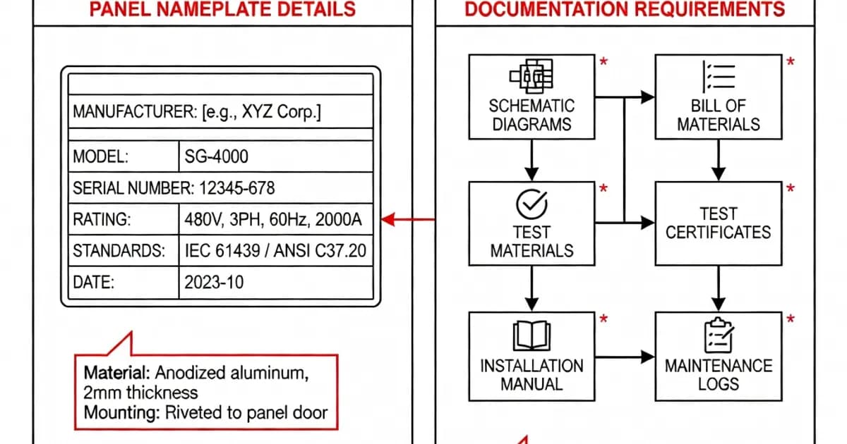
Per IEC 61439-1 Clause 5.6, the assembly nameplate or designation marking must include the minimum information needed to identify the assembly and its ratings. The marking shall be durable, visible, and legible after installation. For a compliant low-voltage assembly, the following data are expected:
- Name or trademark of the manufacturer responsible for the assembly.
- Serial number or unique identification of the assembly.
- Year of manufacture.
- Designation of the assembly, such as type, model, or reference.
- Rated voltage(s), including operational voltage Ur and insulation voltage Ui where applicable.
- Rated current In for the assembly or relevant functional units.
- Rated frequency fr.
- Degree of protection using the IP code in accordance with IEC 60529.
- Additional ratings or limits where needed, such as short-circuit withstand capability, temperature rise limitations, or special environmental restrictions.
Siemens’ IEC standards technical guide shows practical examples of combined IEC 61439-1 and IEC 60204-1 nameplates where trademark, serial number, voltage, current, and other ratings are clearly displayed on the enclosure or door surface [3]. ABB likewise lists manufacturer name, serial number, year, Ur, In, fr, and IP code as minimum elements for its compliant assemblies [1].
The IP code deserves particular attention. IEC 61439 references IEC 60529 for the enclosure protection degree, which identifies protection against access to hazardous parts, solid objects, and water. If the enclosure is marked IP54, for example, that statement must correspond to the actual enclosure design and verified build, not merely the component enclosure datasheet. This is a common audit point during routine verification [1][6][7].
Nameplate placement and legibility requirements
IEC 61439-2 adds practical guidance for power switchgear and controlgear assemblies, including the expectation that the main nameplate be positioned where it is accessible and visible, typically at eye level on the front of the assembly. In industrial practice, this usually means a fixed location on the door, front cover, or a clearly visible adjacent face. The purpose is simple: the panel must be identifiable without opening the enclosure or disturbing its protective integrity [3][4].
For PSC-assemblies, supplementary marking practices are also common. Black-on-white text is typically used for identification, while safety warnings use white-on-red or other high-contrast warning formats. Circuit designations should appear at functional units and terminations so that operators and maintenance staff can trace feeders, outgoing ways, and terminal connections without relying only on drawings [4][6][7].
Good panel design also ensures the nameplate remains readable after installation. If a recessed mounting position, cabinet door furniture, or external barriers obscure the plate, the marking does not meet its practical purpose. Hensel and Hager both stress that identification must remain visible in the final installed condition, not just on the workshop floor [6][7].
How IEC 61439 changed panel identification responsibility
The transition from IEC 60439 to IEC 61439 was not only a technical update; it clarified responsibility. Under IEC 61439, the original manufacturer performs the design verification of the assembly system or design concept, while the assembly manufacturer builds the specific panel, applies the nameplate, and confirms routine verification on the completed assembly. This separation is central to compliance and to traceability in the event of service issues or incident investigation [2][6][7].
In practical terms, a panel builder cannot simply rely on component ratings alone. The nameplate must reflect the verified assembly performance, including the enclosure arrangement, busbar system, thermal behavior, protective measures, and short-circuit withstand capability as assembled. A mismatched nameplate is not a minor labeling issue; it is evidence of a possible design-verification gap.
Documentation required for installation, use, and maintenance
IEC 61439-1 Clause 5.7 requires the assembly manufacturer to supply instructions for installation, use, and maintenance. The documentation package must be sufficient for safe installation and service over the life of the assembly. It should be proportional to the complexity of the panel and the intended user group, but it must always support the declared ratings and verified performance [1][2][6][7].
A complete documentation set typically includes the following:
- Assembly drawings, including general arrangement drawings, single-line diagrams, schematic diagrams, and wiring diagrams.
- List of functional units and components, with circuit references and terminal data.
- Routine verification report, showing the panel passed required inspection and test checks.
- Design verification summary, including relevant test reports, calculations, and evidence for temperature rise, dielectric properties, short-circuit withstand, clearances, creepage distances, and mechanical strength.
- Declaration of conformity, confirming that the completed assembly complies with the IEC 61439 series and any applicable regional requirements.
- Installation, operation, and maintenance instructions.
ABB’s practice guide and Hensel’s IEC 61439 handbook both emphasize that the documentation must support the declared design and the actual assembled panel. The paperwork is not separate from compliance; it is part of compliance [1][7].
Design verification versus routine verification
IEC 61439 distinguishes between design verification and routine verification. Design verification demonstrates that a design concept is capable of meeting the standard’s performance requirements. Routine verification confirms that the actual built panel matches the verified design and is free from assembly defects. This distinction is essential when evaluating nameplate accuracy and documentation completeness [1][2][6][7].
Design verification may be established by testing, comparison with a verified reference design, or assessment/calculation where allowed. It covers aspects such as temperature rise, dielectric properties, short-circuit withstand strength, protective circuit effectiveness, and degrees of protection. Routine verification then checks the final assembly for correct wiring, correct marking, secure connections, protection against electric shock, clearances, and proper labeling. Clause 10 requires verification of marking and IP-related conditions as part of the routine inspection process [1][7].
For the panel builder, this means the nameplate values must be backed by documented design evidence. If the panel is marked with an IP54 rating, the enclosure, seals, door hardware, cable entries, and final assembly must all support that degree of protection. If the nameplate states a rated current of 1600 A, the thermal design and verification basis must support that current under the stated installation conditions.
Typical contents of a compliant documentation pack
A useful way to think about IEC 61439 documentation is as a hierarchy: identity, ratings, verification, and operating instructions. A compliant package often includes the following technical artifacts:
| Document | Purpose | Typical Contents |
|---|---|---|
| Nameplate / designation marking | Identifies the assembly in the field | Manufacturer, serial no., year, type, voltages, current, frequency, IP code |
| General arrangement drawing | Shows physical layout | Dimensions, compartment layout, device arrangement, cable entry points |
| Single-line diagram | Shows electrical power topology | Incoming device, busbar system, feeder circuits, protective devices |
| Schematic / wiring diagram | Supports assembly and troubleshooting | Control circuits, terminal numbering, interlocks, auxiliary contacts |
| Routine verification report | Confirms finished panel conformity | Marking check, continuity, dielectric checks, mechanical inspection, IP-related checks |
| Design verification summary | Proves design compliance | Test reports, calculation notes, reference design evidence, component coordination data |
| Instructions for installation, use, and maintenance | Supports safe lifecycle use | Mounting, torque, cleaning, replacement intervals, spare parts, shutdown steps |
| Declaration of conformity | Formal compliance statement | Applicable standard references, responsible manufacturer, signature, date |
Special requirements for PSC-assemblies
Power switchgear and controlgear assemblies, or PSC-assemblies, are subject to the general IEC 61439-1 requirements and the specific application focus of IEC 61439-2. For these assemblies, the user information package often needs to be more detailed because the panel will typically contain multiple feeders, motor control sections, and coordinated protective functions [2][4].
IOGP S-560, widely used in oil and gas projects, goes further by requiring structured data sheets and circuit schedules for PSC-assemblies. These project specifications typically demand clear feeder identification, equipment schedules, and documentation that aligns the panel nameplate with the individual circuit labels and terminal markings [4]. This approach reduces confusion during commissioning and maintenance, especially in large facilities where many similar boards are installed.
In PSC applications, the assembly manufacturer should ensure that each circuit designation is repeated consistently across the nameplate, door legend, circuit schedule, and as-built drawings. Inconsistent labels are one of the most common causes of maintenance errors.
Common marking and documentation mistakes
In field audits and factory inspections, the most frequent issues are not sophisticated design failures but basic labeling and paperwork gaps. The following problems recur across many industries:
- Missing or incomplete nameplate data, especially year of manufacture, serial number, or rated frequency.
- IP code claimed but not supported by the final enclosure build or cable-entry arrangement.
- Unclear circuit identification, where feeder labels do not match drawings or terminal markings.
- No routine verification record, or a checklist that does not reflect the actual panel configuration.
- Design verification evidence unavailable, particularly for thermal or short-circuit performance.
- Instructions too generic to support safe installation, maintenance, or replacement of components.
Hensel’s and ABB’s guidance both underline the importance of retaining verifications and design evidence, especially when assemblies are built from verified systems rather than fully bespoke designs [1][7]. A well-managed technical file should remain available for the life of the assembly and for any regulatory or customer review period applicable to the project.
Best practices for panel builders
Strong compliance practice combines engineering discipline with good information control. The following methods improve nameplate quality and documentation reliability:
- Use a standardized nameplate template tied to the verified design family.
- Place the main nameplate at eye level and ensure it remains visible after installation.
- Use durable materials such as engraved metal or high-performance polymer labels suited to the environment.
- Cross-check all ratings against the design verification basis before release.
- Match circuit designations across all documents, labels, and terminal markers.
- Generate routine verification checklists digitally to reduce omissions and improve traceability.
- Retain design records and test evidence in a controlled technical file for future reference.
Digital tools can significantly reduce the administrative burden. ABB’s Panel Design Configurator is one example of software that exports verification-related data and supports structured documentation [1]. Siemens also illustrates how compliant product families can ship with standardized marking and documentation formats that simplify installation and inspection [3].
Manufacturer responsibilities and CE compliance
For assemblies sold in the European market, IEC 61439 compliance also supports CE marking obligations where applicable. The assembly manufacturer must issue the declaration of conformity on the basis of the verified design and the completed routine verification. In other words, the CE or conformity statement is not a standalone form; it must reflect real engineering evidence [3][6][7].
The documentation pack should therefore clearly identify the responsible assembly manufacturer, the applied standard edition, the assembly designation, the key ratings, and any limitations on the scope of use. If the assembly is intended for a defined temperature range, altitude, or pollution environment, those limits should be recorded in the technical documentation and, where relevant, referenced on the nameplate or in the installation instructions.
Practical checklist for review before shipment
Before a panel is released, the assembly manufacturer should confirm the following:
- The nameplate is fixed securely and is readable in the installed position.
- The nameplate data match the final verified build.
- All feeder and functional unit labels are consistent with drawings and schedules.
- The routine verification report is complete and signed off.
- The design verification evidence is available and traceable to the assembly type.
- The instruction manual covers installation, operation, maintenance, and any service restrictions.
- The declaration of conformity references the correct IEC 61439 parts and edition.
This is the minimum standard expected of a professional assembly manufacturer. When panels are built for critical infrastructure, process plants, or oil and gas applications, the documentation set is often expanded by project specifications such as IOGP S-560, which demands structured data sheets and circuit schedules beyond the base IEC requirements [4].
Conclusion
Panel nameplates and documentation are core compliance elements under IEC 61439, not optional labels or afterthoughts. The nameplate identifies the assembly and communicates its verified ratings. The documentation package proves how the assembly was designed, built, and verified, and it gives the end user the information needed to install, operate, and maintain it safely. When the nameplate, drawings, verification records, and instructions all align, the panel is easier to audit, safer to use, and better protected against costly errors.
For panel builders, the practical rule is straightforward: if it is not marked correctly and documented clearly, it is not fully compliant. As shown in the ABB, Siemens, Hager, Hensel, and IOGP references, the best assemblies combine robust engineering with disciplined information management [1][3][4][6][7].
References and Further Reading
- ABB: The standard IEC 61439 in practice
- Electrical Engineering Portal: Introduction to IEC 61439
- Siemens: Control Panels - Compliant with IEC Standards
- IOGP S-560: Supplementary requirements for power switchgear and controlgear assemblies
- Related Standards
Frequently Asked Questions
Under IEC 61439-1, every low-voltage switchgear and controlgear assembly should carry a durable nameplate that identifies the assembly and its design limits. At minimum, the plate should show the manufacturer’s name or trademark, assembly type or unique reference, date of manufacture or serial number, rated voltage, rated frequency, rated current, and short-circuit withstand ratings where applicable. In practice, many builders also include IP rating, form of internal separation, and ambient conditions if these affect the verified rating. The marking must remain legible for the assembly’s service life and be fixed in a visible location on the enclosure. If the assembly is a type-tested or design-verified system built from products such as Schneider Electric PrismaSeT, ABB System pro E power, or Siemens Sivacon, the nameplate should still reflect the actual assembled ratings, not only component datasheet values.Not usually. IEC 61439 focuses on the assembly as a whole, so the main nameplate applies to the complete MCC lineup or section. However, feeder cubicles, withdrawable units, and special functional modules may require supplementary identification if they contain different ratings, circuit references, or operating instructions. This is especially useful in motor control centres using withdrawable starters, such as Eaton xEnergy MCC or Schneider TeSys-based buckets, where each unit may have a distinct motor rating, protection setting, or control voltage. Any extra labels should not contradict the main assembly marking. If a compartment has a local disconnect, warning symbol, or arc-flash label, that information should be added as part of the documentation package and site safety labeling, not as a substitute for the assembly nameplate required by IEC 61439.IEC 61439 requires the manufacturer to provide sufficient documentation for correct installation, operation, inspection, and maintenance of the assembly. Typical deliverables include the general arrangement drawing, wiring schematics, single-line diagram, bill of materials, terminal schedules, and operating instructions. The documentation should also state rated data, protection settings or device coordination assumptions, form of separation, IP degree, and any conditions for safe transport, mounting, ventilation, and future extensions. For assemblies incorporating devices such as Schneider Masterpact, ABB Tmax XT, or Siemens 3VA circuit breakers, the documentation should clearly show device settings and coordination tables where relevant. Good practice also includes test records, verification evidence for IEC 61439 design verification, and spares lists. The goal is to allow the installer and user to verify that the delivered panel matches the intended application.The nameplate should state the assembly’s rated operational voltage and, where applicable, rated insulation voltage, frequency, and rated current. Short-circuit performance must also be identifiable, typically through the rated short-time withstand current, rated peak withstand current, or the conditional short-circuit current of a protected circuit. IEC 61439 requires these values to match the verified assembly design, including busbar system, outgoing devices, and protective coordination. For example, if a lineup uses a 50 kA busbar system with molded-case or air circuit breakers from ABB, Schneider Electric, or Siemens, the plate must not claim a higher fault withstand than the verified construction supports. If the assembly is used in a specific environment, such as 400 V, 50 Hz, 65 kA for 1 second, that full rating set should be marked clearly so the end user can compare it with the installation fault level and system requirements.Yes, the documentation pack should include evidence that the assembly complies with IEC 61439 design verification requirements, even if not every test report is handed to the customer in full. The manufacturer should keep and, where appropriate, provide records showing verification by testing, calculation, comparison with a verified design, or assessment of criteria such as temperature rise, dielectric properties, short-circuit strength, clearances, creepage distances, and mechanical operation. This is particularly important for custom-built panels and modified standard systems like Rittal Ri4Power or Siemens Sivacon S4, where the final arrangement may differ from catalog configurations. The documentation should make it clear which verification method was used for each requirement. A complete handover file often includes summary verification sheets, device datasheets, and assembly-specific calculation notes, enabling audits, maintenance, and future modifications without guessing how the rating was established.While IEC 61439’s core marking list centers on identity and electrical ratings, it is best practice to include the enclosure’s IP rating and the form of internal separation if they are critical to installation or maintenance. This is especially relevant for assemblies in dusty, wet, or industrial environments, or where busbar and functional unit segregation affects safety and service continuity. For example, a panel built in a Rittal VX25 enclosure or a Schneider PrismaSeT system may rely on a stated IP55 or Form 4b configuration to meet project requirements. If these characteristics are not shown on the nameplate, they should appear prominently in the documentation and technical schedule. The key rule is consistency: the nameplate, drawings, and verification records must all describe the same assembly, so installers do not confuse catalog enclosure data with the actual built and verified panel.The user instructions should explain safe installation, operation, inspection, maintenance, and any limitations of the assembly. IEC 61439 expects information that enables the end user to keep the panel within its verified ratings and environmental conditions. Instructions should cover mounting orientation, cable entry, tightening torques, ventilation clearances, periodic inspection intervals, replacement parts, and any restrictions on adding feeders or changing protective devices. If the assembly uses equipment such as ABB Tmax XT breakers, Schneider Acti9 auxiliaries, or Siemens SENTRON monitoring modules, the instructions should also include device-specific operating and reset procedures. For withdrawable MCC units, guidance on racking, isolation, and lockout/tagout is essential. Clear instructions reduce the risk of unauthorized modification that could invalidate the design verification, compromise temperature rise performance, or alter short-circuit withstand capability.Standard and custom-built panels both need the same fundamental IEC 61439 identification and technical data, but custom assemblies usually require more detailed documentation because the verified configuration is less obvious. A standard platform panel, such as a factory-configured Schneider PrismaSeT, ABB MNS, or Siemens Sivacon assembly, may be supported by established design verification data and product literature. A custom-built panel often needs project-specific drawings, calculation sheets, protection coordination data, and a clearer declaration of the exact assembly limits. The nameplate must always reflect the final built panel, not a generic system family. If the builder has combined multiple brands or changed enclosure sizes, busbar arrangements, or cooling methods, the documentation must show those deviations and the resulting verified ratings. In short, custom panels demand tighter traceability, while standard panels still require accurate final marking and a complete handover package.
Ready to Engineer Your Next Panel?
Our team of electrical engineers is ready to design, build, and deliver your custom panel solution — fully compliant with international standards.