Seismic Qualification of Electrical Panels
Qualifying panels for earthquake resistance.
Seismic Qualification of Electrical Panels
Seismic qualification of low-voltage electrical panels is a specialized extension of IEC 61439 design verification. IEC 61439 does not prescribe a single global “earthquake test” for all assemblies, but it does require the panel builder to verify mechanical strength, enclosure integrity, dielectric performance, protective circuit continuity, and functional operation under foreseeable service stresses. In practice, seismic qualification combines IEC 61439 mechanical verification with project-specific seismic criteria, often derived from local building codes such as ASCE 7 or from client specifications. As explained in IEC 61439 guidance documents, compliance is not based on assumption; it depends on documented design verification, type testing, comparison with a verified reference design, or assessment by calculation.
For LV assemblies, the relevant IEC framework is IEC 61439-1 for general rules and IEC 61439-2 for power switchgear and controlgear assemblies. Mechanical robustness is addressed mainly through Clause 10.2, which covers strength of materials and parts, and Clause 10.11, which addresses resistance to mechanical impact. The assembly must also continue to meet dielectric requirements under Clause 10.9, protective circuit effectiveness under Clause 10.5, and mechanical operation under Clause 10.12 after the verification process. In other words, seismic qualification is not just about “not falling apart”; it is about preserving safe electrical performance after mechanical stress.
Why seismic qualification matters
Earthquake loading can cause distortion of sheet metal frames, loosening of terminations, busbar displacement, internal conductor fatigue, and loss of enclosure protection. Even when a panel remains physically standing, hidden failures can create serious hazards: phase-to-phase short circuits, loss of protective earth continuity, compromised IP protection, or failure of breakers and contactors to operate correctly. This is why serious seismic qualification focuses on both structural and functional survival.
In many projects, especially in healthcare, data centers, transportation infrastructure, utility substations, and critical industrial facilities, the panel must remain anchored and operable after a design-level seismic event. The requirement is often framed by a peak ground acceleration or by a seismic zone classification. For example, higher-severity qualification programs may reference “Seismic Zone 4” conditions, commonly associated with approximately 0.5g demand in project specifications. That value is not an IEC universal requirement, but it is representative of the type of dynamic loading used in real-world certification programs.
How IEC 61439 treats seismic and dynamic stress
IEC 61439 is fundamentally a design-verification standard. As described in IEC and industry guidance, the manufacturer must prove that the assembly design can withstand normal and abnormal service conditions, including thermal stress, short-circuit forces, and mechanical stress. Seismic loading is usually treated as a mechanical robustness issue rather than a stand-alone mandatory IEC 61439 clause. The most relevant verification points are:
- Clause 10.2 – strength of materials and parts
- Clause 10.5 – protection against electric shock and integrity of protective circuits
- Clause 10.9 – dielectric properties
- Clause 10.11 – resistance to mechanical impact
- Clause 10.12 – mechanical operation
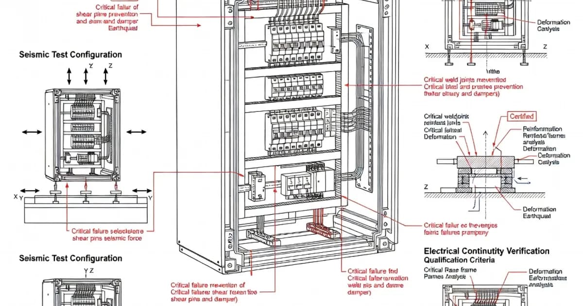
In practice, a seismic assessment may use one or more of the following verification methods: testing on a shake table, calculation by finite element analysis, comparison with a previously verified reference design, or a combination of these methods. As noted in IEC 61439 guidance, the chosen method must be appropriate to the assembly design and must be supported by technical evidence.
Relevant standards and how they fit together
Several standards interact in seismic qualification of panels. IEC 61439 provides the base product framework, while other standards define environmental severity or enclosure durability. The key references are summarized below.
| Standard | Purpose | Relevance to seismic qualification |
|---|---|---|
| IEC 61439-1:2020 | General rules for low-voltage switchgear and controlgear assemblies | Defines design verification requirements, including mechanical strength and functional integrity |
| IEC 61439-2:2020 | Power switchgear and controlgear assemblies | Provides product-specific verification framework for many LV panels |
| IEC 62262:2002 | Degrees of protection provided by enclosures against external mechanical impacts | Defines IK impact ratings such as IK08 and IK10 |
| IEC 60529 | IP code for ingress protection | Confirms that enclosure sealing remains effective after mechanical stress |
| IEC 60068-2-6 / -2-27 / -2-57 | Environmental vibration, shock, and endurance tests | Often used to simulate dynamic mechanical effects related to seismic exposure |
| ASCE 7 | US building code basis for seismic design | Frequently used to define project-specific earthquake loads and qualification criteria |
Per IEC 61439-1 and IEC 61439-2, the panel builder remains responsible for ensuring the assembly performs as intended after the relevant verification. Per IEC 62262, impact protection is expressed using IK codes. Per IEC 60529, ingress protection must still be maintained after mechanical stress if the enclosure is claimed to have a particular IP rating. These standards work together rather than competing with each other.
Mechanical impact, IK ratings, and what they prove
Although earthquake loading is not identical to a local impact test, IEC 62262 is still highly relevant because it classifies enclosure resistance to external mechanical impacts. The IK code indicates how much energy the enclosure can withstand. For example, IK08 corresponds to 5 joules of impact energy. Higher ratings such as IK10 indicate a tougher enclosure shell and better resistance to deformation or cracking.
In a typical IEC 62262 test, the exposed surfaces receive five evenly distributed impacts on each test surface. The intent is to verify that the enclosure retains its safety and protection properties after impact. The enclosure must not suffer damage that compromises IP protection, electrical safety, or the operation of installed equipment. This is especially important for panels installed in public buildings, transport nodes, or industrial environments where accidental impacts can combine with vibration or seismic movement.
However, an IK rating alone does not equal seismic qualification. An IK test is useful evidence of enclosure toughness, but an earthquake introduces cyclic inertia, anchoring loads, component mass effects, and resonant response. That is why full seismic qualification usually requires additional dynamic analysis or test evidence.
What a seismic-qualified panel usually includes
A panel designed for seismic performance typically uses a much more robust mechanical architecture than a standard indoor assembly. Common design features include:
- Rigid base frame with adequate floor anchoring points
- Anchorage system sized for the site-specific seismic demand
- Reinforced cubicles to resist racking and frame distortion
- Flexible busbar connections or expansion links to accommodate relative motion
- Secure component mounting with locking hardware and anti-loosening measures
- Strain relief for wiring to prevent terminal fatigue
- Controlled center of gravity to reduce overturning moment
Industry practice strongly favors low center-of-gravity layouts, rigid base channels, and anchoring arrangements that are matched to the floor structure. Poor anchoring is one of the most common causes of seismic failure. Even a structurally sound enclosure can fail if the anchors, embedments, or floor fixings are not designed for the required shear and uplift forces.
Verification methods used in practice
For seismic qualification, manufacturers and project engineers commonly use one or more of the following methods:
- Shake-table testing to reproduce the seismic response spectrum or acceleration profile
- Finite element analysis to assess stress, deflection, and modal response
- Reference design comparison when the assembly closely matches a previously verified platform
- Component-level verification for breakers, contactors, meters, and support hardware
- Anchorage calculation based on site demand, mass, and floor/foundation characteristics
As noted in practical IEC 61439 guidance, the evidence must be traceable. A statement that a panel is “seismic rated” has little value unless supported by a report, calculation package, or test certificate that identifies the tested configuration, mounting arrangement, mass distribution, and acceptance criteria.
Specification comparison: standard panel versus seismic-qualified panel
| Feature | Standard LV Panel | Seismic-Qualified LV Panel |
|---|---|---|
| Design basis | IEC 61439 design verification for normal service | IEC 61439 plus project-specific seismic verification |
| Anchorage | Typical floor fixing | Engineered anchors sized for seismic shear and uplift |
| Busbar arrangement | Standard rigid supports | Flexible links, bracing, and strain relief |
| Mechanical robustness | Meets general strength requirements | Enhanced frame stiffness and dynamic load resistance |
| Verification evidence | Routine and design verification documents | Routine verification plus test or analysis for seismic demand |
| Typical use | Commercial and industrial installations | Hospitals, transit systems, critical infrastructure, high-risk zones |
Important design details that affect seismic performance
Seismic performance is often determined by small mechanical details rather than by major structural members alone. A panel may appear substantial, but weak internal fixings can still fail under vibration. Particular attention should be paid to the following:
- Terminal integrity: Terminations must remain tight after vibration and shock. Loose lugs can create arcing faults.
- DIN rail and device supports: Control devices, relays, and terminal blocks need secure mounting to avoid disengagement.
- Door hardware: Hinges, locks, and latches must not open or misalign under dynamic displacement.
- Busbar support spacing: Busbar supports must account for inertial forces and short-circuit forces together.
- PE continuity: Protective earth bonds must remain intact throughout the event, per IEC 61439 Clause 10.5.
- Clearances and creepage distances: Deformation must not reduce dielectric separation below required values.
These points matter because seismic loading often reveals weak assembly practices. A panel can pass a basic enclosure check and still fail if an internal conductor pulls free, a PE strap fractures, or a breaker loses mounting torque.
Manufacturer practices and product examples
Major manufacturers typically address seismic requirements through engineered enclosure systems, verified busbar supports, and accessory kits for anchorage and bracing. As documented in manufacturer technical literature and IEC 61439 design guides, seismic claims are usually tied to specific frame families, mounting methods, and installation limits.
| Manufacturer | Example platform | Noted seismic-related features |
|---|---|---|
| Siemens | NXPLUS C or 8DJH panels | FEA-verified mechanical design, robust enclosure frame, high-impact resistance |
| ABB | UniGear ZS1 or UniSec | Vibration-tested designs, flexible busbar arrangements, verified assembly structure |
| Schneider Electric | Okken or Blokset | Seismic qualification options, anchorage kits, reinforced base construction |
| Eaton | Power Xpert UX or xEnergy | Assembly verification under IEC 61439, bracing and mounting options for seismic sites |
| Rittal | VX25 or TS 8 enclosure systems | High IP and IK options, accessories for anchoring and harsh-environment installations |
These examples illustrate an important point: seismic qualification is usually configuration-specific. A manufacturer may offer a qualified frame family, but the exact rating can depend on the selected height, width, internal layout, anchoring scheme, and installed component mass.
Good engineering practice for seismic compliance
Sound engineering practice goes beyond basic compliance documents. It begins at the concept stage with mass distribution, anchor planning, and device arrangement. It continues through design verification and ends with correct installation. The most reliable projects apply the following principles:
- Design for the site demand: Use the project’s seismic acceleration, response spectrum, or zone classification rather than a generic “seismic” label.
- Minimize top-heaviness: Place heavy breakers, transformers, and busbar systems low in the assembly where possible.
- Specify proper anchoring hardware: Select anchors for the actual concrete type, embedment depth, and edge distance.
- Control torsion and racking: Use stiff base members and symmetric bracing where possible.
- Protect conductors: Add slack, loops, or flexible interconnections to absorb displacement without fatigue.
- Document torque values: Fastener torque control is essential for repeatable seismic performance.
- Inspect after installation: Routine verification should confirm PE bonds, clearances, panel alignment, and anchorage integrity, consistent with IEC 61439 Clause 11.
In high-consequence applications, third-party review is often worthwhile. Independent evaluation can confirm that the panel installation, not just the enclosure design, meets the project requirements. This is especially important where local codes or owner standards require evidence of compliance for critical infrastructure.
Relationship between seismic performance, IP rating, and IK rating
Seismic qualification should not be confused with environmental sealing or impact resistance, although these attributes complement one another. An assembly intended for a harsh site may require:
- High IP rating to prevent ingress of dust or water, per IEC 60529
- High IK rating to resist accidental impact, per IEC 62262
- Seismic anchoring and mechanical verification to survive earthquake loading
For example, an enclosure with IP66 and IK10 offers strong protection against dust, water, and accidental impact, but it still needs seismic evaluation if it is installed in a region with significant earthquake risk. Conversely, a panel may be seismically anchored yet still fail to meet ingress protection if doors, gaskets, or cable entry systems are not correctly designed.
Limitations and scope of IEC 61439
It is important to stay precise about what IEC 61439 does and does not do. IEC 61439 establishes a framework for low-voltage assembly verification, but it does not replace local building codes, project seismic criteria, or owner-specific resilience requirements. It also does not automatically certify every installed configuration if the field installation differs from the verified design.
That means a panel builder must pay attention to the actual delivered assembly: the frame size, internal division form, mounting arrangement, number and mass of devices, and the method of anchoring to the structure. If any of these materially change, the original verification may no longer apply without reassessment.
Practical conclusion
Seismic qualification of electrical panels is a combination of good structural design, documented IEC 61439 verification, and project-specific earthquake analysis. The most reliable assemblies are not merely “strong”; they are engineered as systems. That system includes the enclosure, busbars, devices, wiring, protective earth bonding, anchorage, and the installation substrate.
For mccpanels.com readers, the key takeaway is simple: if a low-voltage panel is expected to operate in a seismic region, do not rely on generic enclosure strength alone. Require evidence for mechanical robustness, verify the anchoring strategy, confirm internal retention and PE continuity, and ensure that the final configuration matches the design that was tested or analyzed. When these elements align, IEC 61439 compliance and seismic resilience can be achieved together.
Related Standards
Frequently Asked Questions
Ready to Engineer Your Next Panel?
Our team of electrical engineers is ready to design, build, and deliver your custom panel solution — fully compliant with international standards.