Type Testing vs Routine Verification
Understanding the two levels of verification in IEC 61439.
Type Testing vs Routine Verification
In IEC 61439, the old concept of type testing has been replaced by design verification. This is a major shift in how low-voltage switchgear and controlgear assemblies are validated. Instead of proving compliance only by testing a single prototype, the standard now allows a design to be verified by testing, comparison with a verified reference design, or application of design rules and calculations. As explained in IEC 61439-1 Clause 10, the goal is to confirm that the assembly design meets the performance requirements for safety, thermal performance, dielectric strength, and short-circuit withstand.
By contrast, routine verification applies to every manufactured assembly. Per IEC 61439-1 Clause 11, the assembly manufacturer must inspect and test each unit before delivery to ensure the product was built correctly and that no manufacturing defects compromise safety. In practical terms, design verification proves the design is sound, while routine verification proves the specific assembly was built properly.
This distinction is central to IEC 61439 compliance and is especially important for panel builders, OEMs, and system integrators working with custom low-voltage assemblies.
Why IEC 61439 Replaced “Type-Tested” Terminology
Under the older IEC 60439 framework, manufacturers often marketed products as “type-tested” or “partially type-tested.” IEC 61439 removed that terminology because it was too rigid and did not reflect the reality of modern modular assembly design. A panel may use a proven enclosure, a verified busbar system, and certified functional units, but still require the manufacturer to prove that the complete assembly meets the standard when configured in a specific way. Schneider Electric notes that IEC 61439 introduced a fundamentally different approach: the standard focuses on verified design methods rather than a single pass-or-fail type test model.
This matters because many real-world assemblies are variants of a base design. IEC 61439 allows manufacturers to reuse verified reference configurations, provided the new configuration remains within the validated design envelope. As documented in BEAMA guidance and ABB verification materials, this significantly reduces duplicated testing while maintaining a high level of assurance.
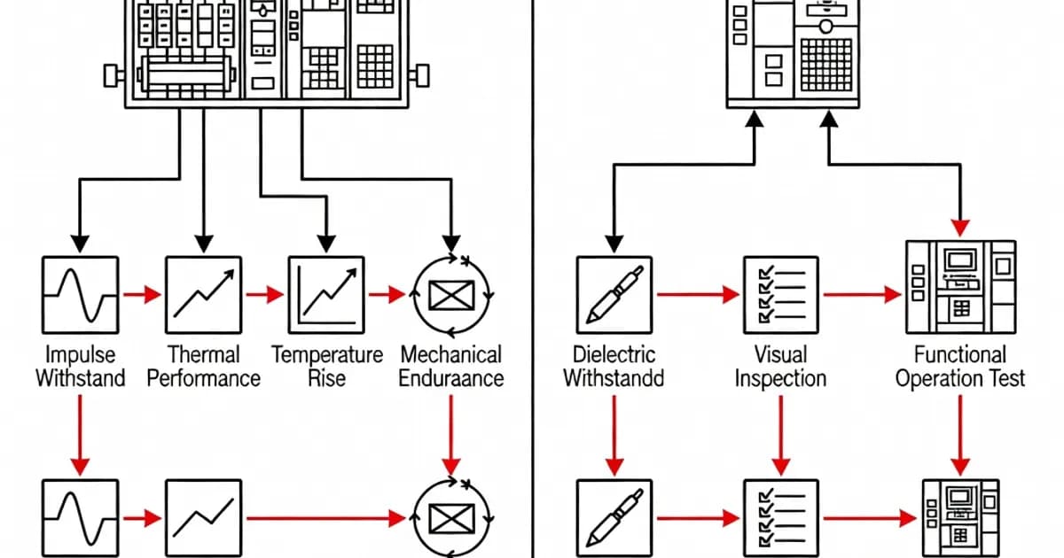
Design Verification Under Clause 10
Design verification is governed by Clause 10 of IEC 61439-1. It covers 12 characteristics that together establish whether the assembly design is fit for service. These characteristics include material strength, degree of protection, clearances and creepage distances, protection against electric shock, incorporation of switching devices, internal electrical circuits and connections, terminals for external conductors, dielectric properties, temperature rise, short-circuit withstand strength, electromagnetic compatibility where relevant, and mechanical operation.
The verification method may vary depending on the characteristic. IEC 61439 permits three approaches:
- Testing of the actual design or a representative configuration
- Comparison with a previously verified reference design
- Assessment by design rules or calculation, such as thermal calculations or short-circuit force evaluation
This flexibility is one of the reasons IEC 61439 is considered more practical than its predecessor. It allows original manufacturers to build verified design libraries and use them across multiple product families, provided the constructional assumptions remain valid.
Key Verified Characteristics in Clause 10
Several Clause 10 items are especially critical in low-voltage panel design.
Temperature rise verification under Clause 10.10 ensures that the internal temperature of the assembly remains within the limits of the installed components and conductors. This can be verified by test or by calculation, but the method must account for rated current, ventilation, ambient temperature, enclosure arrangement, and diversity of loading. For example, when manufacturers use reference designs, they may rely on thermal data from previously tested assemblies rather than performing a full thermal test on every variation.
Short-circuit withstand strength under Clause 10.11 verifies that busbars, supports, and protective circuits can withstand the mechanical and thermal effects of fault current. This is one of the most critical design checks because an inadequate short-circuit design can lead to catastrophic failure. Industry guidance from ABB and BEAMA emphasizes the importance of verifying the main busbar system and critical functional units, especially where multiple outgoing feeders or busbar arrangements are used.
Dielectric properties under Clause 10.9 confirm insulation coordination and clearance integrity. This is not the same as the routine dielectric test performed on finished assemblies. Design verification establishes that the design itself is capable of withstanding the required impulse and power-frequency voltages without breakdown.
Degree of protection is also verified at design stage, typically with reference to IEC 60529. The selected enclosure and sealing arrangement must achieve the declared IP rating for the intended service environment.
Design Verification Methods in Practice
Original manufacturers typically verify a family of products by creating a reference design and then extending the results to variants. Siemens, ABB, Schneider Electric, Eaton, and Rittal all use this principle in their low-voltage assembly systems. Their design manuals and technical literature show how thermal, mechanical, and short-circuit data are reused across product configurations, as long as the new configuration remains within the tested or calculated limits.
For example, a busbar system verified for a certain current rating may be extended to a lower-current configuration if conductor size, support spacing, enclosure geometry, and ventilation conditions are not made more severe. Conversely, a change in busbar arrangement, enclosure size, or outgoing device density may require additional verification. This is why verified design control is a core engineering task, not a one-time document filing exercise.
Routine Verification Under Clause 11
Routine verification is defined in Clause 11 of IEC 61439-1. Unlike design verification, which applies to the design as a whole, routine verification applies to each and every assembly produced. Its purpose is to detect manufacturing faults, incorrect wiring, missed terminations, wrong components, damaged insulation, and assembly defects that could compromise safety or performance.
Routine verification is the responsibility of the assembly manufacturer. In practice, that may be the original manufacturer, a panel builder, or a system integrator assembling a certified platform into a customer-specific configuration. The key requirement is that the final assembly must be checked before it is placed into service.
What Routine Verification Includes
Clause 11 typically includes the following checks:
- Inspection of conductors and wiring to ensure correct routing, identification, and terminations
- Verification of clearances and mounting distances to confirm the assembly matches the verified design
- Protective circuit continuity, ensuring earthing and bonding paths are intact
- Insulation resistance checks, typically referenced to at least 1000 Ω/V in accordance with common practice cited in industry guidance
- Functional testing of switching, interlocking, mechanical operation, and control circuits
- Verification of degree of protection where relevant, such as enclosure assembly integrity and sealing
- Checking labels, warning notices, and technical documentation
Electrical portal guidance and manufacturer documents stress that routine verification is not intended to re-prove design strength. Instead, it checks that the produced unit conforms to the approved design and that no fault was introduced during manufacture or final assembly.
Why Routine Tests Are Limited in Duration
Routine dielectric tests are intentionally short, typically around 1 second in many industrial procedures, because the goal is to confirm insulation integrity and clearances without damaging the assembly. These tests are not designed to subject components to prolonged stress. In particular, sensitive devices such as current transformers, voltage transformers, electronic relays, and control electronics may need to be disconnected or bypassed during routine withstand testing to prevent damage. This is why routine verification is procedural and controlled, not simply a repetition of design verification testing.
Routine checks are also practical. A manufacturing line may produce many variants of a standard platform, and every unit must be verified efficiently. By focusing on critical safety checks, IEC 61439 ensures that routine verification catches workmanship errors without duplicating the full design validation effort.
Comparison of Design Verification and Routine Verification
The two verification stages serve different purposes and are both essential for compliance. The table below summarizes the key differences.
| Aspect | Design Verification (Clause 10) | Routine Verification (Clause 11) |
|---|---|---|
| Purpose | Validate that the assembly design meets IEC 61439 performance and safety requirements | Confirm that each manufactured assembly matches the verified design and is free from production defects |
| Frequency | Once per design, reference design, or design family | Every assembly produced |
| Responsible party | Original manufacturer or design creator | Assembly manufacturer |
| Methods | Testing, comparison, calculation, or design rules | Inspection, measurement, continuity checks, and functional tests |
| Typical examples | Temperature rise, short-circuit withstand, dielectric properties, degree of protection | Insulation resistance, protective conductor continuity, wiring correctness, labels, control operation |
| Outcome | Evidence that the design is suitable for the declared ratings | Evidence that the delivered assembly is correctly built and safe to energize |
Common Standards and Related Documents
The primary standard for low-voltage assemblies is IEC 61439-1:2020, which provides the general rules for low-voltage switchgear and controlgear assemblies. Specific product requirements are addressed in companion parts such as IEC 61439-2 for power switchgear and controlgear assemblies and IEC 61439-3 for distribution boards intended for household and similar applications, generally up to 630 A.
Additional standards often interact with IEC 61439 verification:
- IEC 60529 for degrees of protection provided by enclosures, including IP ratings
- IEC 60947 for low-voltage switchgear and controlgear devices installed within the assembly
- BS EN IEC 61439 national adoptions, including UK annexes and local guidance on internal separation and verification practice
- IEC 62271-200 in medium-voltage applications where internal arc considerations are relevant, though this is not the core low-voltage assembly standard
The practical implication is that a compliant panel is rarely assessed against IEC 61439 alone. The assembly standard governs the complete system, while embedded devices and environmental classifications are covered by related standards.
How Manufacturers Apply IEC 61439 in Real Projects
Major manufacturers build their product platforms around verified designs. Siemens SIVACON systems, ABB low-voltage solutions, Schneider Electric Okken and Blokset assemblies, Eaton Power Xpert UX, and Rittal-based panel systems all rely on combinations of tested reference designs and routine verification on production units. This approach reduces engineering time while preserving compliance.
In practice, a manufacturer may verify the thermal and short-circuit performance of a base design, then use that verification across multiple project variants. The panel builder still has to ensure that the actual build remains within the validated limits. If a customer requests a higher ingress protection rating, a different busbar arrangement, or denser device packing, the builder must check whether the change stays within the verified design family or whether additional verification is required.
Industry guidance also highlights the importance of documenting reference design assumptions. For example, diversity factors, busbar grouping, feeder arrangement, and spacing conditions can materially affect thermal performance and short-circuit withstand. If those assumptions change, the original verification may no longer be valid.
Best Practices for Panel Builders and Engineers
To apply IEC 61439 effectively, panel builders should establish a disciplined verification process from the start of the project.
- Define reference designs early so that variants can be assessed against a proven baseline
- Document all Clause 10 evidence, including test reports, calculations, comparison records, and design assumptions
- Keep routine verification records for each assembly, including inspection sheets, test results, and sign-off records
- Verify critical functional units first, especially busbars, main incomers, and heavily loaded outgoing feeders
- Control component substitutions so that replacement devices do not invalidate thermal or short-circuit data
- Use the correct verification method for the characteristic; do not substitute a routine test for a design verification requirement
- Protect sensitive devices during dielectric testing by disconnecting them where necessary and following the manufacturer’s instructions
These practices reduce nonconformities and help ensure that both the design and the final manufactured assembly can be defended technically and commercially.
What This Means for Compliance and Liability
The compliance implications are significant. A manufacturer that performs excellent routine checks but has no credible design verification cannot claim IEC 61439 conformity. Equally, a design verified once in the laboratory does not automatically make every shipped unit compliant. Both layers are mandatory.
From a liability standpoint, IEC 61439 draws a clear line of responsibility. The original manufacturer is responsible for design verification. The assembly manufacturer is responsible for routine verification of the completed unit. In many modern supply chains, these roles may be split between platform suppliers and panel builders, so contractual documentation should make the responsibilities explicit.
This dual structure is one reason IEC 61439 is considered more robust than IEC 60439. It closes the gap between prototype validation and factory output control.
Conclusion
Type testing is no longer the governing concept in IEC 61439. It has been replaced by design verification, which allows manufacturers to prove the safety and performance of a low-voltage assembly design through testing, comparison, or calculation. Routine verification then confirms, on every manufactured assembly, that the product matches the verified design and is free from assembly faults.
For panel builders and engineers, the message is clear: design verification proves the concept, routine verification proves the build. A compliant panel needs both. When implemented correctly, IEC 61439 provides a practical, scalable framework for delivering safe, reliable, and technically defensible low-voltage assemblies.
References and Further Reading
- Electrical Engineering Portal: Routine tests for low-voltage switchgear
- ABB: The standard IEC 61439 in practice
- CHYF: Type test vs routine test practical guide
- Schneider Electric: IEC 61439, more than just an upgrade
- PBSI on the Net: Type-testing gives way to verified designs
- BEAMA Guide to Verification for BS EN IEC 61439-2
- PDS Tekpan: Routine verification appendix to IEC 61439-1
- Video resource on IEC 61439 verification concepts
Related Standards
Frequently Asked Questions
Ready to Engineer Your Next Panel?
Our team of electrical engineers is ready to design, build, and deliver your custom panel solution — fully compliant with international standards.