Variable Frequency Drive Sizing and Selection
How to size and select VFDs for panel integration.
Variable Frequency Drive Sizing and Selection
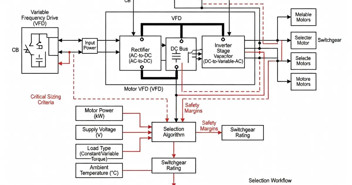
Variable frequency drives, or VFDs, are among the most thermally and electrically demanding components placed inside low-voltage panel assemblies. For that reason, VFD sizing cannot be treated as a simple motor horsepower match. In an IEC 61439-compliant panel, the drive, its feeder protection, the enclosure ventilation, the busbar system, the wiring, and the outgoing motor cable all affect the verified performance of the assembly. Per IEC 61439-1 and IEC 61439-2, the panel builder must ensure that the complete assembly is verified for temperature rise, dielectric properties, short-circuit withstand, clearances, creepage distances, protection against electric shock, and degree of protection after integration of the equipment.
As documented in ABB’s IEC 61439 workbook and IEC 61439 guidance material, VFD integration is especially sensitive because drives convert a meaningful portion of input power into heat. Typical drive losses are commonly in the range of 3% to 5% of rated power, and that heat must be removed without exceeding the temperature-rise limits of the assembly. In practice, that means the “right” VFD is not only the one that can run the motor, but the one that can be safely installed, protected, cooled, and verified inside the selected enclosure system.
Understanding the IEC 61439 Framework for VFD Panels
IEC 61439 defines low-voltage switchgear and controlgear assemblies up to 1000 V AC and 1500 V DC. The standard moved the industry away from the older type-tested panel concept toward verified assemblies with clear division of responsibility between the original manufacturer and the assembly manufacturer. Schneider Electric’s summary of the standard is useful here: the specifier defines the application requirements, while the assembly manufacturer must deliver a verified panel that satisfies them under the intended conditions of service.
For VFD panels, the key implication is simple: the drive cannot be selected in isolation. The assembly must be verified as a whole or by permissible design rules and comparisons. IEC 61439 allows certain verification by calculation and comparison for assemblies up to 1600 A under defined conditions, but the rules are strict. Similar verified assemblies must share the same functional unit group, construction type, dimensions, power-loss characteristics, and outgoing circuit arrangement, otherwise a full verification may be required.
Why VFDs are challenging for panel builders
VFDs generate heat, harmonics, and switching transients. They also rely on adequate clearances, creepage distances, and cable routing to preserve EMC performance. Unlike many contactor-based feeders, a VFD compartment can create localized hot spots and high-frequency noise sources. This means the panel builder must consider thermal management, power quality, and electromagnetic compatibility at the same time.
In a correctly engineered assembly, the enclosure’s IP rating remains valid after the drive is installed, but only if all gland plates, cable entries, doors, seals, and ventilation components are specified and installed in a way that maintains the declared degree of protection. IEC 60529 governs the IP code itself, while IEC 61439 governs whether the complete assembly remains compliant after build.
How to Size a VFD Correctly
The most reliable starting point is the motor nameplate current, not just the motor kilowatt rating. In many applications, especially pumps, fans, and variable torque loads, the VFD should be selected with margin above the motor full-load current to accommodate overloads, service factors, ambient derating, and duty cycle. A practical rule is to select a drive rated at least 10% to 20% above the motor demand when the application includes frequent starts, acceleration demand, or high inertia. For many industrial drives, a 150% overload capability for 60 seconds is expected, but the exact overload profile must be checked against the manufacturer’s duty rating.
As a design discipline, the drive selection should include:
- motor rated current and voltage
- required overload capacity and acceleration torque
- ambient temperature at the panel location
- switching frequency and associated losses
- drive arrangement: standalone, common DC bus, or multi-drive
- line reactor, EMC filter, or harmonic filter requirements
- cable length between drive and motor
Where the supply voltage is 400 V or 690 V, the VFD must match the rated operational voltage of the assembly and must not exceed the phase-to-phase voltage limitations of the equipment. Per IEC 61439-1, rated operational voltage is limited to 1000 V AC for low-voltage assemblies. Impulse withstand voltage must also be appropriate to the installation; for example, 690 V systems may require a Uimp level such as 12 kV depending on the installation category and the equipment design.
Specification table for VFD selection inside an IEC 61439 assembly
| Selection item | Typical requirement | Why it matters |
|---|---|---|
| Drive current rating | Motor FLA with 10% to 20% margin | Prevents nuisance overload trips and supports duty-cycle demand |
| Overload capacity | Commonly 150% for 60 s, depending on manufacturer | Ensures starting and transient torque capability |
| Rated voltage | Must match assembly Un and motor supply | Maintains dielectric and insulation coordination compliance |
| Temperature rise impact | Account for 3% to 5% drive losses | Critical for panel thermal verification |
| Short-circuit rating | Icw at least equal to prospective fault level | Protects the assembly under fault conditions |
| EMC mitigation | Filters, shielded cable, proper segregation | Reduces conducted and radiated interference |
| Cooling method | Natural ventilation or forced cooling | Maintains allowed temperature rise in the enclosure |
Temperature Rise and Cooling Requirements
Temperature rise verification is one of the most important issues in VFD panels. Per IEC 61439-1, temperature-rise limits must not be exceeded under rated current and declared ambient conditions. A commonly cited limit is 70 K for terminals and 105 K for bare copper busbars, with reference ambient temperature not exceeding 35°C. For VFDs, this is particularly important because the drive itself adds thermal load to the enclosure.
When a drive dissipates 3% to 5% of its rated power as heat, the thermal effect can become substantial in a multi-drive lineup. A 30 kW drive may contribute roughly 900 W to 1500 W of heat, and a bank of several such drives can quickly exceed the passive cooling capability of a standard enclosure. That is why many verified VFD panels use top-mounted extract fans, filtered ventilation, air-conditioning units, or segregated drive compartments with dedicated airflow paths.
IEC 61439 permits temperature-rise verification by testing, by calculation, or by comparison with a similar verified assembly, but only under strict conditions. The comparison method is acceptable when the construction, dimensions, power losses, functional unit arrangement, and outgoing circuits are sufficiently similar. For larger assemblies, or when the design deviates materially from a previously verified configuration, a physical test is often the safest route.
Practical thermal design measures
- Place high-loss VFDs away from the upper plenum to avoid recirculation of hot air.
- Use segregated compartments when multiple drives are installed in one lineup.
- Derate equipment if ambient temperature exceeds 35°C.
- Verify total losses from drives, reactors, transformers, and auxiliary supplies before finalizing enclosure size.
- Use forced ventilation when the combined losses approach the enclosure’s passive dissipation limit.
In many industrial panel systems, the cooling design is as important as the drive selection itself. As noted in manufacturer guidance for IEC 61439 assemblies, a panel that is electrically correct but thermally underdesigned is not a compliant solution.
Short-Circuit Withstand and Protective Coordination
VFD feeders must be coordinated with the prospective short-circuit current available at the installation point. IEC 61439 requires the assembly to have a short-circuit withstand capability, often expressed as Icw, that is at least equal to the fault level the panel may experience for the declared duration, such as 1 second. In industrial applications, this may range from 35 kA to 65 kA at 1 s or higher, depending on the upstream transformer and network.
The feeder protective devices must also be selected carefully. For VFD incomers and outgoers, circuit breakers and switching devices should have breaking capacity and making capacity suitable for the installation. In practice, panel designers often coordinate air circuit breakers or molded-case circuit breakers so that Icu, Ics, and the assembly’s short-time withstand ratings are consistent with the fault study. This is not optional. If the protective device trips or fails outside its rating, the integrity of the verified assembly is lost.
Per IEC 61439-2, the assembly manufacturer remains responsible for ensuring the verified short-circuit performance of the complete panel, including busbars, supports, incoming devices, outgoing feeders, and any VFD branch circuit components. If the VFD panel uses a manufacturer’s tested ecosystem, the short-circuit verification is usually more straightforward. If components from multiple vendors are mixed, the verification burden increases significantly.
Neutral Sizing, Harmonics, and Power Quality
VFDs are a major source of harmonic distortion. Even when a drive is properly installed, the rectifier front end can inject harmonics into the supply system, especially the 5th, 7th, 11th, and 13th orders, along with triplen harmonics in certain arrangements. This has direct consequences for neutral sizing, transformer loading, and meter selection.
IEC-based guidance for harmonic-rich installations recommends that the neutral conductor be sized at 100% of phase cross-section up to 16 mm² and at least 50% with a minimum of 16 mm² above that, with larger sizes or non-copper conductors evaluated separately. In many VFD-heavy panels, engineers go beyond the minimum and specify an oversized neutral or even a 200% neutral in particularly harmonic-intensive sections. This is especially relevant where multiple single-phase auxiliary loads coexist with drive loads.
Harmonic mitigation may include line reactors, DC chokes, passive filters, active filters, or multipulse drive arrangements. The choice depends on the allowable total harmonic distortion, the upstream transformer capacity, and the sensitivity of other loads connected to the same bus. In facilities with power quality requirements, the panel should also incorporate metering capable of recording THD and harmonic order distribution.
Recommended power quality functions for VFD panels
- THD measurement for current and voltage
- Harmonic analysis to at least the 31st order
- Active energy metering with IEC 61557-12 compliant devices
- Event logs for undervoltage, overvoltage, and drive trips
- Optional logging for demand and load profile monitoring
Per IEC 61557-12, multifunction meters used in low-voltage assemblies can provide the power quality visibility needed for commissioning and ongoing diagnostics. In critical installations, this data is often the difference between diagnosing a nuisance fault in minutes rather than hours.
EMC, Clearances, Creepage, and Wiring Discipline
VFDs use high-frequency switching, which means electromagnetic compatibility must be considered from the earliest design stage. The enclosure layout should keep power wiring, motor cables, control wiring, communication cables, and metering circuits segregated. Cable shields should be terminated correctly, and the drive manufacturer’s recommendations for grounding and cable routing should be followed closely.
IEC 61439 requires the assembly to maintain insulation coordination, including clearances and creepage distances appropriate to the rated voltage and pollution degree. These distances are not merely paper values; they are affected by conductor arrangement, terminal spacing, and the choice of accessories. If a VFD is retrofitted into an existing panel, the builder must confirm that the original spacing philosophy still holds after the new equipment is installed.
Temperature, pollution degree, and altitude can all affect dielectric performance. If the panel is used in a harsh industrial environment, the designer should confirm the enclosure material, terminal arrangement, and ventilation method are consistent with the declared environment. A panel with good electrical ratings but poor cable segregation will often fail EMC expectations during commissioning.
Selection of Enclosure, IP Rating, and Internal Arc Performance
The enclosure selection for a VFD panel should reflect both environmental protection and thermal performance. IEC 60529 defines the degree of protection, such as IP31, IP43, or IP55. Higher IP ratings usually improve resistance to dust and water ingress, but they can also reduce natural ventilation. For that reason, a high-IP VFD panel often requires forced cooling or a heat exchanger to stay within temperature-rise limits.
Internal arc withstand is another important consideration in industrial drive panels. IEC 61641 provides a method for internal arc classification and testing. Where the installation risk profile justifies it, the panel should be specified with arc containment across all relevant compartments and access directions. In high-energy systems, a fault inside a drive section can be severe, so arc-resistant construction and proper compartmentation are valuable risk-reduction measures.
As seen in major panel system documentation from Siemens, ABB, Schneider Electric, Eaton, and Hager, modern low-voltage assemblies increasingly combine compact form, verified temperature-rise behavior, and compartmentalization. The right enclosure is not just a box; it is part of the verified system.
Comparison of Common VFD Panel Design Priorities
| Design priority | Low-risk approach | High-demand industrial approach |
|---|---|---|
| Drive selection | Size to motor FLA with modest margin | Size for overload duty, ambient derating, and future expansion |
| Cooling | Natural ventilation | Forced ventilation or dedicated cooling |
| Harmonics | Basic line reactor | Active or passive filtering, neutral oversizing, harmonic monitoring |
| Short-circuit strength | Standard feeder protection | Full coordination with fault study and verified Icw |
| Enclosure | Standard IP31/IP43 cabinet | High-IP or arc-resistant assembly with thermal design validation |
| Verification method | Comparison with similar verified unit | Full test or robust verification package for the exact build |
Common Mistakes in VFD Sizing and Selection
One of the most common mistakes is treating kilowatt rating as the only selection criterion. Motor power alone does not capture overload profile, line voltage, ambient temperature, or the effect of the application duty cycle. Another frequent error is ignoring losses in a multi-drive lineup. A panel with several medium-size drives may appear electrically modest but can produce enough heat to force a redesign of the enclosure cooling system.
A second mistake is underestimating harmonics. If the panel contains several VFDs, the neutral, busbar, transformer, and upstream protection may need to be reviewed for harmonic loading. A third mistake is assuming that because an enclosure is IP-rated, it is automatically suitable for a VFD. High ingress protection can conflict with thermal management unless the ventilation strategy is deliberately engineered.
Finally, many retrofits fail because the panel builder does not revisit the original IEC 61439 verification basis. If the functional unit arrangement changes materially, or if a much higher-loss drive is substituted, the original verification may no longer apply. In those cases, the builder should perform new verification by test, comparison, or calculation as permitted by the standard.
Practical Checklist for Specifying a VFD Panel
- Confirm the motor current, voltage, overload requirement, and duty cycle.
- Check the assembly rated voltage, impulse withstand, and short-circuit withstand.
- Calculate total thermal losses from drives and auxiliaries.
- Choose enclosure cooling to keep the assembly within IEC 61439 temperature-rise limits.
- Verify cable segregation, EMC practices, and protective earth continuity.
- Review neutral sizing and harmonic mitigation measures.
- Confirm the IP rating remains valid after all gland plates and vents are installed.
- Specify power quality metering where drive monitoring is required.
- Ensure the final build is verified to IEC 61439, not merely assembled from suitable parts.
Conclusion
Variable frequency drive sizing and selection for panel integration is fundamentally a systems engineering task. The drive must be electrically compatible with the motor and supply, but it must also fit the verified IEC 61439 assembly in terms of temperature rise, fault withstand, insulation coordination, EMC, and environmental protection. When those factors are addressed together, the result is a safer, more reliable, and easier-to-commission panel.
For
Related Panel Types
Related Components
Frequently Asked Questions
Ready to Engineer Your Next Panel?
Our team of electrical engineers is ready to design, build, and deliver your custom panel solution — fully compliant with international standards.