Capacitor Banks & Reactors in Power Factor Correction Panel (APFC)
Capacitor Banks & Reactors selection, integration, and best practices for Power Factor Correction Panel (APFC) assemblies compliant with IEC 61439.
Overview
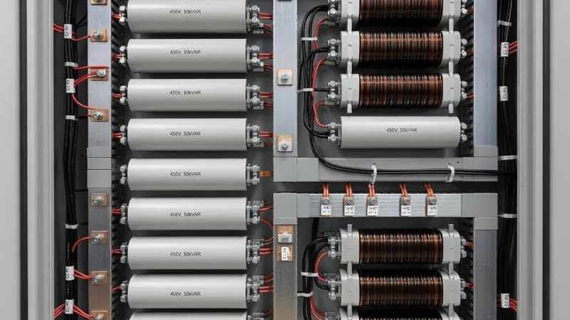
Capacitor banks and reactors are the core power-quality elements of a Power Factor Correction Panel (APFC), designed to reduce reactive power demand, improve displacement power factor, and stabilize voltage profiles in industrial and commercial installations. In practical APFC assemblies, the component set typically includes metalized polypropylene capacitor banks, detuned reactors, discharge resistors, pre-charge or inrush limiting devices, contactors or thyristor switching modules, protection fuses, and intelligent power factor controllers. For highly dynamic loads such as variable-speed drives, lifts, welding lines, and process machinery, thyristor-switched capacitor steps provide fast, transient-free correction; for nonlinear networks with harmonics, detuned reactors are used to prevent resonance and to protect capacitors from excessive harmonic current. From an engineering standpoint, selection must be based on line voltage, harmonic spectrum, short-circuit level, required kvar output, ambient temperature, ventilation limits, and the permissible current loading of the busbar system. Capacitor banks are commonly rated at 230 V, 400 V, 440 V, 480 V, or 525 V systems, with step sizes from 5 kvar to 50 kvar and total panel ratings extending from 25 kvar to more than 1000 kvar. Reactors are typically specified by detuning factor, such as 7%, 14%, or tuned solutions for harmonically severe systems, and must be matched to the capacitor’s current and insulation class. Reactor temperature rise, copper losses, and enclosure derating are critical because the APFC cabinet often operates with elevated internal heat due to continuous reactive current and switching losses. Compliance is governed by IEC 61439-1 and IEC 61439-2 for low-voltage switchgear and controlgear assemblies, with verification of temperature rise, dielectric properties, clearances and creepage, short-circuit withstand strength, and protective circuit continuity. The component devices themselves are selected in accordance with IEC 60831 for shunt power capacitors, IEC 60947-4-1 for switching devices, and IEC 60947-2 for protective circuit breakers where MCCBs or ACBs are used as incomers. If the APFC panel includes communication, monitoring, or energy metering, integration with Modbus RTU/TCP, BACnet, or SCADA/BMS systems is common, enabling alarms for overtemperature, overcurrent, stage failure, and capacitor end-of-life indications. In real-world installations, coordination with the upstream feeder is essential. The incomer may be an MCCB or ACB, and each capacitor step is usually protected by gG/gL fuses or dedicated MCBs, depending on the design. Where higher fault levels are present, the assembly must be verified for short-circuit ratings such as 25 kA, 36 kA, 50 kA, or higher, matching the site prospective fault current. For panels installed in dusty, humid, or warm utility rooms, enclosure selection, forced ventilation, and thermal derating become decisive for long-term reliability. Patrion designs APFC panels with properly coordinated capacitor banks and reactors to ensure low-loss operation, stable compensation under harmonic stress, and robust integration into modern power distribution systems across factories, data centers, commercial buildings, and utility substations.
Key Features
- Capacitor Banks & Reactors rated for Power Factor Correction Panel (APFC) operating conditions
- IEC 61439 compliant integration and coordination
- Thermal management within panel enclosure limits
- Communication-ready for SCADA/BMS integration
- Coordination with upstream and downstream protection devices
Specifications
| Property | Value |
|---|---|
| Panel Type | Power Factor Correction Panel (APFC) |
| Component | Capacitor Banks & Reactors |
| Standard | IEC 61439-2 |
| Integration | Type-tested coordination |
Other Components for Power Factor Correction Panel (APFC)
DOL/star-delta/reversing starters, overload relays, Type 2 coordination
Branch protection 16A–1600A, thermal-magnetic or electronic trip
Energy meters, power quality analyzers, CT/VT, communication gateways
Overcurrent, earth fault, differential, generator protection relays
Other Panels Using Capacitor Banks & Reactors
Bespoke panel assemblies for non-standard requirements — special ratings, unusual form factors, multi-function combinations.
Active or passive harmonic filtering to mitigate THD from non-linear loads. Tuned LC filters, active filters, or hybrid configurations.
Fixed or automatic capacitor bank assemblies for bulk reactive power compensation in industrial and utility applications.
Frequently Asked Questions
Ready to Engineer Your Next Panel?
Our team of electrical engineers is ready to design, build, and deliver your custom panel solution — fully compliant with international standards.