ACB vs MCCB: Selection Criteria for Panel Design
Choosing between air circuit breakers and moulded case circuit breakers.
ACB vs MCCB: Selection Criteria for Panel Design
Choosing between an Air Circuit Breaker (ACB) and a Moulded Case Circuit Breaker (MCCB) is one of the most important decisions in low-voltage panel design. Under IEC 61439, the breaker is not selected in isolation: it must be coordinated with the enclosure, busbar system, temperature-rise limits, short-circuit withstand capability, internal separation form, and the intended duty of the assembly. In practice, ACBs are normally used for main incomers and high-current feeders, while MCCBs are preferred for outgoing feeders where compact size, lower cost, and space efficiency matter most.
For panel builders, the correct choice affects more than just ratings. It influences available fault level, thermal performance, maintenance access, arc-flash strategy, withdrawability, and whether the final assembly can be verified by test, comparison, or design rules. Per IEC 61439-1 and IEC 61439-2, the assembly manufacturer remains responsible for the verified performance of the complete system, not just the individual breaker.
Understanding the Functional Difference Between ACBs and MCCBs
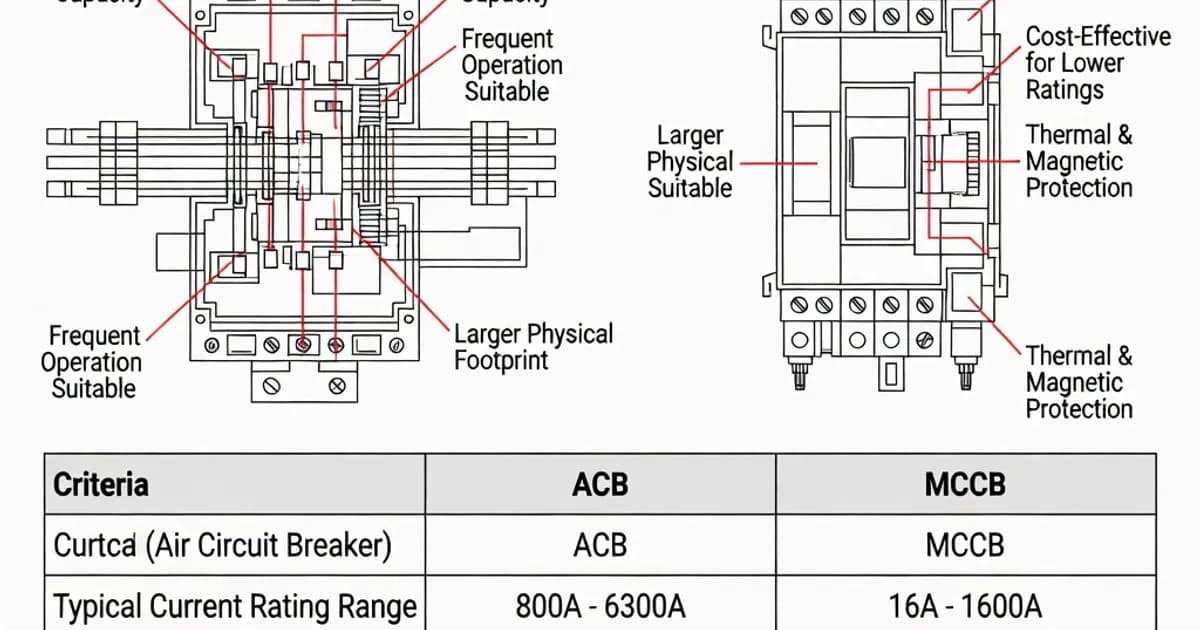
An ACB is designed for higher current applications, typically from 800 A up to 6300 A in modern low-voltage switchboards. It is commonly withdrawable, features extensive protection setting adjustability, and supports maintenance operations such as racking out, inspection, and component replacement. As documented in Siemens, ABB, and Schneider Electric design literature, this makes the ACB the preferred device for incomers, bus couplers, and large feeders where continuity of service and operating flexibility are critical.
An MCCB is a more compact device, typically used from 16 A up to 1600 A, though many panel designs restrict outgoing use to 630 A or similar practical limits to manage heat dissipation, wiring density, and panel depth. MCCBs are widely used for outgoing feeders, motor feeders, distribution circuits, and compact panels where cost and space are major drivers.
From an IEC 60947-2 perspective, both ACBs and MCCBs are circuit-breaker types, but their mechanical construction and practical application differ significantly. ACBs generally provide higher breaking and withstand performance, deeper setting granularity, and better maintenance options. MCCBs offer a smaller footprint and lower acquisition cost, but with less flexibility for large main incomers.
Selection Criteria Under IEC 61439
IEC 61439 does not prescribe a rule such as “always use an ACB above X amps.” Instead, it requires the assembly to be verified for thermal performance, short-circuit withstand, dielectric properties, and protective circuit integrity under the actual configuration used. That means breaker selection must follow the assembly’s verified limits.
Per IEC 61439-1 Clause 8.6.1, current-carrying capability must be verified so that the temperature rise of accessible parts and internal conductors remains within limits. Commonly cited verification values include 70 K for terminals and around 105 K for busbars above a 35°C reference ambient, depending on material and application. In practical design terms, this means a high-current ACB incomer may require larger busbars, better ventilation, and greater spacing than an MCCB-based outgoing section.
Short-circuit performance is governed by IEC 61439-2 Clause 10.10. The assembly must be verified by test, comparison with a reference design, or calculation/design rules. In the breaker context, the designer must ensure that the prospective short-circuit current at the installation point does not exceed the breaker’s rated breaking capacity and that the assembly’s short-circuit withstand rating Icw is adequate for the declared duration, commonly 1 s or 3 s.
As ABB’s IEC 61439 workbook and BEAMA guidance emphasize, the protective device, the busbar arrangement, the enclosure, and any non-protected conductors must all be considered together. Non-protected conductors are limited in length under the standard’s design rules, and the interface between breaker and busbar must be documented and validated.
Key Technical Facts and Specifications
The most relevant technical metrics for ACB and MCCB selection are rated current, short-circuit withstand, breaking capacity, physical size, thermal impact, and maintainability. These parameters determine whether a breaker is suitable for a main incomer, bus-section, motor control feeder, or end distribution circuit.
| Parameter | ACB | MCCB | Relevant Standard or Clause |
|---|---|---|---|
| Typical current range | 800 A to 6300 A | 16 A to 1600 A, often used up to 630 A in panel outgoings | IEC 60947-2; IEC 61439-1 Clause 8.6 |
| Short-circuit withstand | Typically 100 kA to 200 kA at 415 V | Typically 36 kA to 100 kA depending on frame size | IEC 61439-2 Clause 10.10; IEC 60947-2 |
| Breaking capacity | High Icu/Ics, often with Ics = 100% of Icu in premium ranges | Ics commonly 50% to 100% of Icu depending on product class | IEC 60947-2 |
| Physical size | Larger, often withdrawable | Compact, fixed or plug-in | IEC 61439-1 Annex C |
| Maintenance | Higher serviceability, often with draw-out mechanism and visible isolation | Usually sealed construction, limited maintenance | IEC 61439-1 Clause 10.13 |
| Typical panel role | Main incomer, generator incomer, bus coupler, high-duty feeder | Outgoing feeder, motor feeder, sub-distribution | IEC 61439 application practice |
In panel design, a 630 A MCCB may be perfectly suitable as a feeder device, but if the assembly includes multiple loaded circuits, its effective current-carrying capacity can be reduced by diversity, grouping, and thermal interaction. The research notes an example where an outgoing MCCB rated In = 630 A is derated to Inc = 620 A when other circuits are unloaded, which illustrates the importance of real installation conditions rather than nameplate values alone.
Rated Current, Diversity, and Thermal Design
Thermal design is one of the decisive factors in ACB versus MCCB selection. IEC 61439-1 requires the panel builder to verify that the temperature rise of the assembly remains within permissible limits under rated current conditions. This is especially important in compact enclosures with multiple outgoing breakers or in designs with limited natural ventilation.
ACBs are often selected because they can tolerate and manage higher currents without excessive thermal stress in the device itself, particularly when used with appropriately sized busbars and cable terminations. Their protection units are typically adjustable, enabling coordination with downstream feeders and improved selectivity.
MCCBs can also be used in high-density panels, but the designer must account for heat buildup around the device, cable lugs, cable bends, and adjacent functional units. As summarized in BEAMA guidance and practical IEC 61439 interpretation, the assembly manufacturer must verify the configuration in the exact arrangement or use a proven reference design with equivalent spacing, losses, and enclosure conditions.
Short-Circuit Withstand and Breaking Capacity
Short-circuit performance is the other major differentiator. The breaker’s rated breaking capacity, Icu and Ics, is governed by IEC 60947-2, while the assembly’s ability to survive fault forces is verified under IEC 61439-2 Clause 10.10. The two ratings are related but not identical.
An ACB used as a main incomer typically provides higher withstand and interruption capability. It is designed to handle severe fault energy at the origin of the installation, where prospective fault current is usually highest. Many modern ACBs are rated for fault levels up to 100 kA or more, with premium devices reaching 200 kA at 415 V in certain applications.
An MCCB can also have excellent breaking performance, especially in premium frame sizes, but its practical use in panel design is more constrained by compactness, heat, and feeder duty. For lower-duty outgoing circuits, an MCCB’s interruption performance is often more than sufficient and economically preferable.
Where the assembly includes non-protected conductors, IEC 61439 design rules become critical. The research highlights the commonly referenced 3 m limitation for non-protected conductors. In practice, this means the layout between the breaker and downstream protection or busbar sections must be carefully controlled so that fault energy does not exceed the design assumption.
Dimensions, Separation Form, and Panel Architecture
Physical integration is often the deciding factor in real panel projects. ACBs are physically larger and often require withdrawable construction, particularly in assemblies with Form 3B or Form 4 separation. This supports segregation between busbar compartments, functional units, and terminals, improving serviceability and reducing the risk of accidental contact during maintenance.
MCCBs are much more compact and are frequently installed in fixed or plug-in arrangements. They are a natural fit for feeder compartments in Form 2 or Form 3a assemblies where density is high and service intervention is less frequent.
IEC 61439-1 Annex C defines the forms of internal separation. The form selected should reflect the required continuity of service, maintenance strategy, and safety expectations. For high-availability switchboards, a withdrawable ACB in a Form 4b section is often the preferred solution. For smaller distribution boards, a Form 2 or Form 3a arrangement with MCCBs can be fully adequate and more space-efficient.
Protection, Adjustability, and Coordination
Protection coordination is another important reason to choose ACBs for incomers. ACBs typically offer a broader range of adjustable long-time, short-time, instantaneous, and earth-fault protection settings. This enables selective coordination with downstream MCCBs or fuses, helping maintain supply to healthy circuits during faults.
MCCBs also offer adjustable trip units in many modern product ranges, but the range of adjustment and the sophistication of discrimination logic is usually more limited than that of a high-end ACB. For a large LV switchboard, especially one feeding critical loads, the incomer breaker must often be tuned for both protection and continuity of service. As documented in manufacturer design manuals from Siemens, ABB, and Schneider Electric, that is one of the core reasons ACBs remain the standard choice for main incomers.
When selectivity is required, the panel designer should verify time-current coordination curves, manufacturer discrimination tables, and the thermal-magnetic or electronic trip settings for the full cascade chain. This is particularly important in mixed systems combining ACB incomers with MCCB outgoing feeders.
IP Rating, Enclosure Integrity, and Arc Flash Considerations
Breaker selection should also be aligned with enclosure protection and arc-flash strategy. IEC 60529 governs IP ratings, but the assembly must also survive short-circuit events without degrading the declared protection level. This is especially relevant in high-energy panels where an ACB incomer may see substantial arc fault stress.
The research notes that both internal IP and external IP levels may be specified, such as IP31C internally and IP54 externally, depending on the installation environment. However, the panel builder must ensure that the chosen breaker arrangement, cabling, ventilation, and shuttering do not compromise the declared protection after assembly and testing.
Arc containment is increasingly specified alongside IEC 61439 using IEC TR 61641. In high-duty assemblies, particularly those using ACBs as incoming devices, it is common to specify arc-resistant construction, arc venting paths, and mechanical barriers. JIP33 supplementary specifications also highlight shutters and mechanical isolation features for improved safety during maintenance.
Typical Product Positioning from Major Manufacturers
Major manufacturers broadly follow the same application logic. Siemens 3WL ACBs are used for high-current incomers and can reach up to 6300 A, with very high short-circuit withstand levels and withdrawable design. Siemens 3VA MCCBs are compact feeder devices, commonly used up to 1600 A, with high breaking capacity in a smaller footprint.
ABB’s Emax 2 ACB family serves as a main incomer solution with high current ratings and strong short-circuit performance. ABB’s Tmax XT MCCB range is positioned for feeders and distribution circuits, typically up to 630 A in many practical panel applications. ABB’s low-voltage switchgear literature also reinforces the IEC 61439 verification responsibilities for the assembly manufacturer.
Schneider Electric’s Masterpact MTZ series is a flagship ACB range for critical incomers and arc-aware applications, while the ComPact NSX family covers a wide spread of MCCB feeder duties. Eaton’s Power Xpert UX and NZM products follow the same pattern: ACBs for high-duty incomers and MCCBs for compact outgoing circuits.
These product examples matter because IEC 61439 compliance is not achieved by selecting a rated breaker alone. The breaker must be integrated into a verified assembly with suitable busbar dimensions, enclosure performance, separation form, and short-circuit rating.
Practical Selection Guidance for Panel Designers
A good rule of thumb is simple: select an ACB when the circuit is the main incomer, the current is typically 800 A or higher, the fault level is severe, or maintenance and withdrawability are important. Select an MCCB when the circuit is an outgoing feeder, the current is lower, the panel must remain compact, or cost and installation simplicity are priorities.
For panel builders working to IEC 61439, the final decision should be confirmed through a verification route. If the arrangement is close to an existing proven design, comparison or design rules may be sufficient. If the arrangement is new, or if the current level exceeds about 1600 A, temperature-rise testing becomes especially important. The research also notes the practical industry guidance that ambient conditions should normally be referenced to a 35°C average unless the installation specifies otherwise.
Where multiple outgoing feeders are crowded into a single section, MCCBs can quickly become thermally limiting. In that case, using an ACB at the incomer and distributing through sub-feeder sections may improve reliability and ease verification. Conversely, forcing an ACB into a small feeder compartment can waste space and add unnecessary cost.
Common Design Mistakes to Avoid
One common mistake is treating the breaker rating as the only design criterion. A 1600 A MCCB does not automatically make a 1600 A feeder suitable if the enclosure, cable terminations, or busbar system cannot dissipate the heat or withstand the fault energy.
Another frequent error is using a legacy IEC 60439 mindset. IEC 61439 replaced the older framework and introduced clearer responsibilities for the original manufacturer and the assembly manufacturer. The final tested arrangement, not just the component catalogue, determines compliance.
A third mistake is ignoring maintenance access. In high-duty switchboards, a withdrawable ACB with shutters, interlocks, and clear isolation positions can significantly reduce downtime and improve safety. In a heavily populated outgoing section, however, an oversized ACB can create unnecessary depth, cost, and wiring complexity.
Finally, designers sometimes overlook coordination with downstream devices. An incomer ACB with poorly coordinated MCCB feeders can create nuisance tripping or inadequate discrimination. Always check manufacturer selectivity tables and verify the fault level at each node in the system.
Summary: When to Use Each Device
Use an ACB for main incomers, generator incomers, bus couplers, and any application where current is high, fault levels are severe, and maintainability matters. Use an MCCB for outgoing feeders, smaller subcircuits, motor feeders, and compact distribution panels where space and cost are key drivers.
Under IEC 61439, the correct answer is not determined by device category alone. It is determined by the verified performance of the complete assembly. The best design is the one that meets temperature-rise limits, short-circuit withstand requirements, internal separation expectations, and service needs with the smallest practical footprint and the highest achievable reliability.
References and Further Reading
- ABB IEC 61439 Workbook
- ABB: Low Voltage Switchgear and IEC 61439 Presentation
- BEAMA Guide to Verification under BS EN IEC 61439-2
- Related Panel TypesMain Distribution Board (MDB)
Primary power distribution from transformer to sub-circuits. Rated up to 6300A. Houses main incoming breaker, bus-section, and outgoing feeders.
Power Control Center (PCC)High-capacity power distribution for industrial facilities. Controls and distributes incoming power to MCC, APFC, and downstream loads.
Related Components
Frequently Asked Questions
Choose an ACB when the outgoing or incomer circuit needs higher continuous current, adjustable protection, and better coordination in a main distribution board. In IEC 60947-2 terms, ACBs are typically used at higher ratings, commonly from 800 A up to 6,300 A, with electronic trip units offering long-time, short-time, instantaneous, and earth-fault protection. They are especially suitable for incomers, bus couplers, generator feeders, and where selective coordination with downstream devices is critical. MCCBs are better suited for smaller feeders and final circuits, usually up to 1,600 A depending on the frame, where space, cost, and simplicity matter more than extensive settings. For IEC 61439 panel design, the choice also depends on short-circuit withstand, temperature rise, and compartment space. If your assembly requires draw-out maintenance, remote operation, or networked protection, an ACB is often the more robust solution.The main technical difference is in construction, protection flexibility, and application range. An air circuit breaker uses air as the arc-quenching medium and is designed for higher current ratings, more adjustable trip settings, and superior selectivity in distribution systems. A moulded case circuit breaker is a compact, enclosed device with fixed or adjustable thermal-magnetic or electronic protection, intended for lower to medium current applications. Under IEC 60947-2, both are circuit-breakers, but ACBs generally have higher breaking capacity options, more advanced trip units, and are often withdrawable. MCCBs are typically more compact and cost-effective, making them ideal for feeder protection, motor circuits, and local distribution. In panel design, the difference also affects mechanical layout, heat dissipation, accessibility, and maintenance strategy. Siemens 3WA/3WL and Schneider Masterpact are common ACB families; Schneider Compact NSX, ABB Tmax XT, and Siemens 3VA are common MCCB examples.Compare the breaker’s rated ultimate short-circuit breaking capacity (Icu) and rated service short-circuit breaking capacity (Ics) against the prospective short-circuit current at the point of installation. IEC 60947-2 requires these values to be stated by the manufacturer, and the selected device must interrupt the maximum fault current safely at the system voltage. In practice, ACBs are usually selected where fault levels are high and coordination margins are important, such as main incomers near transformers or large generators. MCCBs can also have very high Icu values, but their performance depends strongly on frame size and trip unit. Do not rely on current rating alone; a 630 A MCCB may have a lower Icu than a 2,500 A ACB, or vice versa depending on the product line. For IEC 61439 assemblies, verify the verified short-circuit strength of the whole panel, not just the breaker, including busbars, supports, and connections.Usually yes, because ACBs provide more precise and wider-ranging trip adjustments, which improves time-current coordination with downstream MCCBs, MCBs, and fusegear. Many modern ACB electronic trip units allow long-time, short-time, instantaneous, and earth-fault settings with delay bands that support selective grading. This is particularly valuable in main LV switchboards where maintaining continuity of supply is essential. MCCBs can also be selectively coordinated, especially when using electronic trip versions and manufacturer coordination tables, but their adjustment range is generally narrower. IEC 60947-2 addresses selectivity and back-up protection concepts, while IEC 61439 requires the assembly designer to verify the performance of the complete system. In a well-designed panel, an ACB incomer feeding MCCB sub-feeders can provide better discrimination during faults, reducing the risk of upstream tripping and improving availability for critical loads such as data centers, hospitals, and process plants.ACBs are often the preferred choice for generator incomers and bus couplers because these positions typically require high continuous current, robust short-time delay, and strong selective coordination. Generator sources can produce lower but more sustained fault currents than utility sources, so the breaker must support adjustable short-time protection and withstand coordination with AVR, protection relays, and synchronizing controls. IEC 60947-2 ACBs with electronic trip units are well suited to these duties. Bus couplers also benefit from the withdrawable design available on many ACBs, which simplifies maintenance and testing in main switchboards. MCCBs may be used in smaller generator sets or compact switchboards, but they are less common where the system architecture demands advanced protection logic or high operational duty. When designing under IEC 61439, consider the duty cycle, fault level, and mechanical endurance. For critical installations, ACBs from Schneider Masterpact, ABB Emax 2, or Siemens 3WA are widely used in these roles.Breaker choice has a direct impact on both thermal performance and physical layout. ACBs are larger, generate more internal heat under load, and require greater clearance for terminals, shutters, racking mechanisms, and cable bending radii. That means more panel width, depth, and ventilation planning in the IEC 61439 assembly. MCCBs are more compact and generally easier to package in feeder compartments, which can improve power density and reduce enclosure size. However, a higher-density arrangement of MCCBs can still create local hot spots if cable termination, busbar spacing, or diversity assumptions are poor. IEC 61439 requires verification of temperature rise for the complete assembly, so the designer must account for breaker losses, busbar losses, and ambient conditions. In practice, an ACB-based incomer section often needs dedicated top or bottom cable chambers, while MCCB outgoing sections allow more circuits per vertical space. Thermal modeling, manufacturer derating data, and tested assembly configurations are essential.Yes, but only if the MCCB’s ratings and coordination characteristics fully satisfy the application. For smaller main distribution boards, a high-frame MCCB may be adequate as an incomer if its continuous current, breaking capacity, selectivity, and operational endurance meet the system requirements. Many modern MCCBs with electronic trip units, such as Schneider Compact NSX, ABB Tmax XT, or Siemens 3VA, can handle demanding feeder duties. However, compared with ACBs, MCCBs usually offer less extensive adjustment, fewer accessories for advanced control, and less robust maintenance features for repeated operation. If the incomer must manage transformer protection, generator switching, bus coupling, or high selectivity requirements, an ACB is often the better engineering choice. Under IEC 60947-2 and IEC 61439, the final decision should be based on verified system data, not just breaker frame size. Always confirm Icu/Ics, mechanical endurance, and the assembly’s verified short-circuit withstand.A practical selection checklist starts with the load current, prospective fault level, and required level of selectivity. Next, determine whether the breaker is serving an incomer, bus coupler, feeder, motor, or generator circuit. For IEC 60947-2 compliance, compare continuous current rating, Icu, Ics, trip unit type, insulation voltage, and operating duty. For IEC 61439 panel design, verify temperature rise, short-circuit withstand, creepage and clearance, accessibility, and internal separation. Then assess space, maintenance access, remote operation, communication needs, and lifecycle cost. ACBs are usually justified where high current, advanced protection, or frequent switching is expected. MCCBs are preferred where compact size, lower cost, and straightforward feeder protection are priorities. Also consider manufacturer ecosystem compatibility, such as Schneider Masterpact with NSX coordination, ABB Emax 2 with Tmax XT, or Siemens 3WA with 3VA. The best choice is the one that satisfies electrical performance, panel verification, and operational maintenance requirements together.
Ready to Engineer Your Next Panel?
Our team of electrical engineers is ready to design, build, and deliver your custom panel solution — fully compliant with international standards.