Digital Twin Technology for Panel Design
Using digital twins for panel simulation and lifecycle management.
Digital Twin Technology for Panel Design
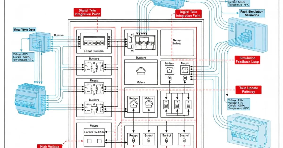
Digital twin technology is changing how engineers design, verify, and maintain low-voltage panel assemblies built to IEC 61439. In practical terms, a digital twin is a virtual representation of a physical assembly that captures geometry, electrical loading, thermal behavior, enclosure characteristics, and operating data across the asset lifecycle. For panel builders, this means design decisions can be checked early against IEC 61439 requirements before metal is cut or busbar material is ordered.
Under IEC 61439-1 and IEC 61439-2, compliance is established through design verification rather than the older type-test mindset. That verification covers a defined set of characteristics, including temperature rise, short-circuit withstand strength, dielectric properties, protective circuits, clearances and creepage distances, degree of protection, mechanical operation, and electromagnetic compatibility. Digital twins help model many of these characteristics virtually, reducing the number of physical prototypes needed while still supporting conformity to the standard. Per IEC 61439-1 Clause 10, design verification is the central compliance framework, and Clauses 10.9, 10.10, 10.11, and 10.12 are especially relevant to simulation-led workflows.
Why digital twins matter in IEC 61439 panel projects
Low-voltage switchgear and controlgear assemblies are increasingly expected to be both compliant and optimized. A digital twin allows the design team to evaluate thermal loading, air paths, busbar sizing, enclosure segregation, mounting arrangements, and device coordination before the first assembly is built. As documented in manufacturer guidance from ABB, Siemens, Schneider Electric, and Hensel, this approach supports earlier risk detection and more efficient verification planning.
The main advantage is that the digital model can be used as a source of truth throughout the project. In the design phase, it supports verification of the assembly against IEC 61439. During commissioning, it can guide routine tests and installation checks. During operation, it can hold maintenance, asset, and event data for lifecycle management. This is particularly valuable for critical installations such as hospitals, data centers, process plants, and infrastructure systems, where downtime and thermal overloading have high consequences.
IEC 61439 design verification and the role of simulation
IEC 61439-1:2020 establishes 12 design verification characteristics. For digital twin workflows, the most commonly modeled items include:
- Strength of materials and parts under Clause 10.2.
- Degree of protection under Clause 10.2, assessed using IEC 60529.
- Clearances and creepage distances under Clause 10.3.
- Protection against electric shock and integrity of protective circuits under Clauses 10.4 and 10.5.
- Incorporation of switching devices and components under Clause 10.7.
- Internal electrical circuits and connections under Clause 10.7.
- Terminals for external conductors under Clause 10.7 and IEC 60947-7-1.
- Dielectric properties under Clause 10.9 or related verification requirements depending on the assembly design.
- Temperature rise limits under Clause 10.10 in the cited research context, with thermal verification commonly aligned to IEC 60890 methods.
- Short-circuit withstand strength under Clause 10.11.
- Electromagnetic compatibility under Clause 10.10 in the cited research context, especially where auxiliary electronics and communication modules are present.
- Mechanical operation under Clause 10.12.
Exact clause numbering can vary depending on how a national or industry document summarizes the verification items, but the essential point is consistent: the digital twin must support the design verification evidence package defined by IEC 61439-1 and IEC 61439-2. IEC 61439 allows verification by testing, comparison with a verified reference design, and assessment/calculation where appropriate. That flexibility is what makes simulation valuable.
How a digital twin supports specific verification tasks
Temperature-rise verification is one of the clearest use cases. IEC 61439 requires that the assembly operate within permissible temperature limits under its rated load. In practice, simulation tools often apply IEC 60890 methods for thermal calculations, using conductor sizing, enclosure dimensions, ventilation openings, segregation, installation conditions, and ambient temperature assumptions. The result helps determine whether the design can remain within the standard’s temperature-rise limits without excessive margin loss.
Short-circuit withstand is another major application. Finite element analysis and engineering calculations can model the mechanical and thermal stresses imposed by short-circuit currents on busbars, supports, and connections. This is especially important for verifying Icw, Icc, and related withstand ratings. In many assemblies, the digital twin can help determine whether spacers, bracing, and conductor geometry are sufficient before destructive testing is considered.
Degree of protection can also be assessed virtually. Using enclosure geometry and component placement, the model can predict whether the panel meets IP requirements under IEC 60529. That matters for dusty industrial environments, washdown areas, and outdoor installations where ingress protection affects reliability as well as safety.
Clearances and creepage distances are easiest to model when the digital twin includes accurate 3D device geometry and mounting data. This helps engineers validate spacing around terminals, busbars, and control wiring early in the layout process. Likewise, protective circuit continuity can be validated by checking bonding paths, fault-current paths, and connection points within the modeled assembly.
Key standards used alongside digital twins
IEC 61439 does not stand alone. A practical digital twin workflow typically references several companion standards and manufacturer documents.
| Standard or Document | Primary Role in Digital Twin Panel Design | Typical Use |
|---|---|---|
| IEC 61439-1 / IEC 61439-2 | Core design verification requirements for LV assemblies | Temperature rise, short-circuit withstand, dielectric performance, IP, mechanical operation |
| IEC 60890 | Thermal calculation method for assemblies | Temperature-rise modeling and heat dissipation studies |
| IEC 60529 | IP code classification | Enclosure ingress protection assessment |
| IEC 60947 series | Requirements for incorporated devices | Switchgear, protective devices, and terminals such as IEC 60947-7-1 |
| Manufacturer verification guides | Application-specific interpretation and calculation support | Reference designs, software inputs, thermal derating, and assembly rules |
As shown in ABB’s IEC 61439 practice guide and Siemens’ technical guidance, software-assisted verification works best when it is anchored to proven device data and manufacturer-supplied design limits. Hensel and Schneider Electric similarly emphasize that digital tools should support, not replace, sound engineering judgment and documented verification evidence.
Busbar sizing, RDF, and load diversity
One of the most valuable benefits of a digital twin is the ability to model busbar loading realistically. IEC 61439 and related industry guidance recognize the rated diversity factor (RDF) as a key parameter for determining how much of the installed load is likely to be simultaneous. For main busbars and certain critical sections, designers may use RDF = 1.0 where full loading must be assumed. In other parts of the assembly, diversity can reduce calculated thermal stress if the operating profile is well understood and properly documented.
JIP33 S-560v16 and manufacturer design tools use this concept to improve sizing accuracy, especially where multiple feeders, intermittent loads, or variable-speed drives are present. In a digital twin, the RDF is not just a spreadsheet input. It directly influences thermal maps, hotspot predictions, and conductor utilization. That makes the twin far more useful than a static rating table.
Lifecycle management beyond design verification
Digital twins do not stop at the factory acceptance stage. Once the panel is commissioned, the virtual model can continue to support lifecycle management. This is where the concept becomes more than a design aid and turns into an operational asset.
Lifecycle applications can include monitoring of internal temperature, door operation, fan status, device health, insulation condition, communication availability, and maintenance intervals. In advanced systems, the twin can store configuration history, firmware versions, settings changes, and event logs. This supports faster troubleshooting and better traceability when modifications are made after installation.
For panel assemblies, lifecycle management is especially useful for components and features linked to IEC 61439 verification, including:
- Dielectric properties and insulation condition, relevant to routine inspection and maintenance planning.
- Mechanical operation of switching and isolating devices.
- Protective circuits and equipotential bonding continuity.
- External conductor terminals modeled according to IEC 60947-7-1.
- Auxiliary and communication circuits that support monitoring and diagnostics.
Siemens notes in its technical guidance that supplementary data from digital models can support compliance documentation and operational engineering. ABB and Schneider Electric similarly position digitized panel design as a way to connect engineering, commissioning, and maintenance in one information chain.
Comparison of verification methods in panel design
| Verification Method | Typical Use | Strengths | Limitations |
|---|---|---|---|
| Physical testing | Final proof for critical characteristics | Direct evidence, widely accepted | Costly, time-consuming, often destructive for short-circuit tests |
| Reference design comparison | Repeatable assemblies and standardized platforms | Fast and efficient when a verified baseline exists | Depends on strict similarity and documented design rules |
| Calculation and simulation | Thermal, mechanical, and spatial verification | Early design optimization, fewer prototypes | Requires high-quality inputs and validated methods |
| Digital twin with lifecycle data | Design, commissioning, and operation | Best overall visibility, supports maintenance | Needs disciplined data governance and model updates |
In practice, the best compliance strategy combines these methods. A digital twin can reduce the number of prototypes and guide the assembly toward a compliant design, but the final evidence package still needs correct verification records and routine test results where required by IEC 61439.
Industry examples of digital twin-enabled panel design
Siemens integrates digital engineering workflows into control panel design, enabling supplementary data that supports IEC standards compliance and system verification. Their technical guidance highlights the use of digital information for design consistency and lifecycle documentation.
ABB promotes digitized switchboard design through its “Smart Panels” approach, with tools and documentation that help engineers verify temperature rise, busbar arrangement, and assembly performance in line with IEC 61439-1 and IEC 61439-2. ABB’s workbook on IEC 61439 in practice gives useful examples of how verification evidence can be assembled efficiently.
Schneider Electric uses EcoStruxure Power Design to simulate panel configurations, thermal performance, and short-circuit coordination. Its IEC 61439 commentary emphasizes that the standard is more than an update; it is a new approach to engineered verification and documentation.
Eaton supports LV assembly engineering with software that models diversity, busbar ratings, and withstand performance. This is particularly helpful for multi-feeder systems where load profiles vary significantly.
Rittal and allied enclosure platforms focus heavily on enclosure thermal behavior and IP-related design considerations. That makes their digital workflows relevant where enclosure geometry and ventilation directly affect IEC 61439 verification outcomes.
Best practices for implementing a digital twin workflow
To get real compliance value from a digital twin, panel builders should treat it as a structured engineering process, not a visualization tool. The following practices are widely used in successful IEC 61439 projects:
- Start with complete project data: load schedules, fault levels, ambient conditions, installation method, ventilation strategy, and site constraints.
- Use verified component models: include manufacturer data for devices, busbars, terminals, and enclosures.
- Model thermal behavior early: apply IEC 60890-based calculations before final layout freeze.
- Assume full load where needed: use RDF = 1.0 for critical sections unless diversity is clearly justified.
- Keep protective circuits robust: maintain sound bonding and earthing continuity throughout the design.
- Respect terminal rules: use IEC 60947-7-1 compliant terminals and avoid unnecessary parallel conductor arrangements unless the design permits them.
- Plan for routine verification: dielectric and functional checks should be mapped from the beginning, not added at the end.
- Update the twin after commissioning: reflect as-built changes, settings, and maintenance records.
Industry guidance also recommends keeping non-protected conductors short and controlled, with attention to auxiliary circuit routing and segregation. In many assemblies, limiting exposed or non-protected internal conductor lengths and maintaining clear documentation reduces both compliance risk and troubleshooting time.
What digital twin technology does not replace
Digital twins are powerful, but they do not eliminate engineering responsibility. They do not replace correct component selection, manufacturer instructions, assembly workmanship, or required routine verification. They also do not override the need to validate assumptions such as ambient temperature, airflow restrictions, or real fault level data from the installation site.
For that reason, the most credible IEC 61439 approach is hybrid. Use the digital twin to predict, optimize, and document. Then confirm the final assembly with the appropriate test and inspection steps required by the standard and the project specification. That combination produces a more efficient and more defensible compliance process.
Practical benefits for panel builders and end users
When implemented well, digital twin technology delivers measurable benefits across the full panel lifecycle:
- Reduced design iteration time.
- Earlier detection of thermal and clearance issues.
- Better short-circuit robustness planning.
- Improved documentation for IEC 61439 verification files.
- Lower dependence on costly prototype builds.
- Faster commissioning and change management.
- Improved maintainability through asset-level data continuity.
Reported industry experience suggests that digital twin-led design can cut engineering time significantly, often by 30 to 50 percent on repeatable projects, while also improving confidence in compliance. The exact result depends on the complexity of the assembly, the quality of input data, and the maturity of the software environment.
Conclusion
Digital twin technology has become a practical enabler for IEC 61439-compliant panel design. It supports thermal modeling, short-circuit verification, enclosure assessment, and lifecycle management in a single engineering framework. More importantly, it helps panel builders move from reactive compliance toward predictive design assurance.
For low-voltage switchgear assemblies, the best results come from using the digital twin as part of a disciplined IEC 61439 process: define the requirements, model the assembly accurately, verify the critical characteristics, and keep the as-built data current. Done correctly, this approach improves safety, reduces design risk, and makes compliance more efficient from concept through operation.
References and Further Reading
ABB: Workbook - The standard IEC 61439 in practice
IEC 61439 switchgear overview and application notes
Hensel: Guide to design and assembly according to IEC/EN 61439
Siemens: IEC standards technical guide for control panels
Related Components Touch panels, visualization, remote monitoring, data logging Programmable logic controllers, remote I/O, fieldbus communicationFrequently Asked Questions
Ready to Engineer Your Next Panel?
Our team of electrical engineers is ready to design, build, and deliver your custom panel solution — fully compliant with international standards.