Forms of Internal Separation (Form 1 to Form 4b)
Complete guide to forms of separation in panel assemblies.
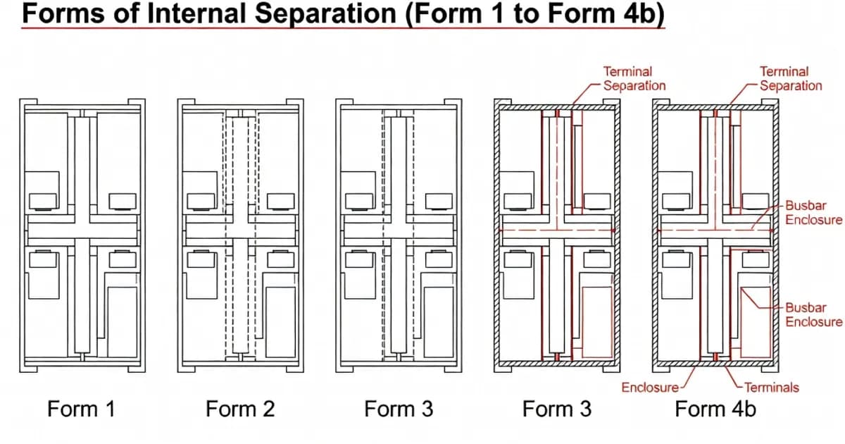
Forms of Internal Separation (Form 1 to Form 4b)
Forms of internal separation define how a low-voltage switchgear and controlgear assembly is divided into internal compartments by means of barriers or partitions. Under IEC 61439-1 and IEC 61439-2, the purpose of internal separation is to reduce the risk of direct contact with live parts, limit the spread of solid foreign bodies, and improve maintenance safety by isolating busbars, functional units, and outgoing terminals from one another. As set out in IEC 61439-2 Table 104, the standard recognises Forms 1, 2, 3, and 4, with subcategories a and b where applicable.
In practical design terms, the selected form affects accessibility, maintenance, uptime, cable routing, and the extent of isolation between feeders. It does not, by itself, make a switchboard arc-proof. Arc fault containment must be specified and verified separately, and only where agreed between manufacturer and user, because the forms of separation described in IEC 61439 address internal partitioning, not full arc fault performance. Per IEC 61439-1 Clause 8.4, the minimum goal between adjacent live compartments is protection at least to IPXXB and IP2X depending on the interface and access route.
What internal separation means in IEC 61439
IEC 61439 uses the term “forms of internal separation” to describe how the assembly interior is divided into distinct spaces. The basic elements are:
- Busbars, which distribute power through the assembly.
- Functional units, such as outgoing feeders, motor starters, or VSD compartments.
- Terminals for external conductors, where incoming and outgoing cables are connected.
The degree of separation is achieved through metal or insulating barriers, partitions, or enclosed device housings. Clause 8.4 of IEC 61439-1 permits barriers and partitions to be metallic or non-metallic, and also recognises insulation such as sleeving and coatings where appropriate. The key requirement is that the selected internal arrangement is verified for the intended form and that accessible surfaces meet the relevant protection levels, especially IPXXB against finger access and IP2X against solid object ingress.
In the UK, BS EN 61439-2 is aligned with IEC 61439-2 but is commonly expressed in industry guidance with additional “Type” terminology for Form 4 arrangements. This can be useful when comparing manufacturer catalogues, but the core IEC designation remains Form 1 through Form 4b.
Forms of separation at a glance
| Form | Busbars | Functional units | Outgoing terminals | Typical application |
|---|---|---|---|---|
| Form 1 | No separation | No separation | No separation | Simple, low-cost assemblies where maintenance access is limited and the enclosure IP rating provides primary protection |
| Form 2a | Separated from functional units | Separated from busbars | Not separated from busbars | Basic segregation with moderate serviceability |
| Form 2b | Separated from functional units | Separated from busbars | Separated from busbars | Improved maintenance safety and cleaner cable management |
| Form 3a | Separated from functional units | Separated from each other | Terminals separated from busbars, but not from each other | Feeder isolation where access to one unit should not expose adjacent units |
| Form 3b | Separated from functional units | Separated from each other | Separated from busbars and from other terminals | Higher operational continuity and better segregation during maintenance |
| Form 4a | Separated from functional units | Separated from each other | Terminals in a separate compartment accessible from the functional unit compartment | Critical installations requiring strong feeder segregation with practical access |
| Form 4b | Separated from functional units | Separated from each other | Each terminal set in an individual enclosed compartment, fully separated | Highest degree of internal separation; often used in hospitals, data centres, and other high-availability sites |
Form 1
Form 1 is the simplest configuration. There is no internal separation between busbars, functional units, or terminals for external conductors. All active parts are arranged within a common enclosure space, so protection depends primarily on the enclosure’s ingress protection rating and the assembly’s construction. As noted in IEC guidance and manufacturer documentation, Form 1 provides the least compartmentalisation and the least protection against incidental contact during maintenance.
This form is often acceptable for small, low-complexity installations where space, budget, and simplicity matter more than service continuity. However, it is rarely appropriate where feeders must be maintained with the board energised or where reduced risk of disturbance between circuits is important. In modern low-voltage distribution, Form 1 is usually the least preferred choice unless a specific application justifies it.
Form 2
Form 2 introduces one of the most useful improvements in switchboard design: separation of busbars from functional units. This reduces the likelihood that maintenance work on a feeder exposes the main distribution system. IEC 61439-2 distinguishes between Forms 2a and 2b.
Form 2a separates busbars from functional units, but the terminals for external conductors are not separated from the busbars. This arrangement gives a moderate level of segregation and is generally used where incoming or outgoing termination access is not required during normal service.
Form 2b adds separation of the terminals from the busbars as well. In practice, this creates a safer and more serviceable board because the cable connection zone is isolated from the main distribution zone. As documented in ABB’s IEC 61439 workbook and BEAMA guidance, this is a common stepping stone toward higher forms of segregation in industrial and commercial assemblies.
For many standard installations, Form 2b is a good balance between cost and safety. It offers improved maintenance discipline without the complexity of full compartmentalisation seen in Forms 3 and 4.
Form 3
Form 3 builds on Form 2 by separating functional units from one another as well as from the busbars. This is a significant operational advantage because a fault, service intervention, or replacement in one outgoing feeder is less likely to affect adjacent feeders. IEC 61439-2 provides the subcategories 3a and 3b to distinguish how the terminals are arranged.
Form 3a separates terminals from the functional units, but the terminals themselves are not separated from one another or from the busbars. This can be suitable where the main concern is to isolate the feeder mechanism from the distribution bars, while retaining a shared cable termination zone.
Form 3b goes further by separating terminals from the busbars and from other terminals. This is frequently specified where multiple feeders run close together and where maintenance access to one circuit must not disturb the others. In many industrial switchboards, Form 3b is regarded as the minimum preferred arrangement when uptime and maintainability are priorities.
Industry guidance from BEAMA and several manufacturer manuals shows that Form 3b is often selected for process plants, hospitals, and larger commercial distribution systems because it improves fault isolation and reduces the risk of accidental cross-contact between cable sets.
Form 4
Form 4 provides the highest degree of internal separation defined by IEC 61439. It retains the Form 3 requirement that busbars are separated from functional units and that functional units are separated from one another, but it also adds separation of terminals for external conductors from the associated functional unit. This is a critical distinction: in Form 4, the cable termination area is treated as its own segregated space, which supports safer maintenance and better operational continuity.
Form 4a places terminals in a separate compartment that is still accessible from the functional unit compartment. This arrangement improves safety and access control while keeping maintenance practical.
Form 4b provides the highest level of segmentation. Each set of terminals is enclosed in an individual compartment, fully separated from the associated functional unit and from other terminal sets. According to manufacturer literature from Siemens, ABB, Schneider Electric, and Eaton, Form 4b is commonly chosen for demanding applications where selective maintenance, enhanced personnel protection, and maximum circuit segregation are required.
Form 4b does not mean “arc-proof” by default. It means the assembly has the highest standard form of internal separation defined in IEC 61439. If arc resistance or internal arc containment is needed, that performance must be specified and verified separately under the relevant product standard or manufacturer test regime.
Protection requirements, clearances, and access safety
IEC 61439-1 Clause 8.4 establishes the protection expectations for separation between live parts and accessible areas. In particular, the arrangement between adjacent functional units must prevent direct contact by at least IPXXB, and protection against solid foreign bodies is generally expected at IP2X or better, depending on the location and access path. In practical terms, this means a finger-safe barrier arrangement and resistance to entry by objects of at least 12.5 mm where applicable.
Barriers and partitions may be metallic or non-metallic. The standard also permits insulation methods such as sleeving or coatings in defined cases, but these must be applied consistently and verified as part of the design. BEAMA guidance stresses that “internal separation” is not just a layout concept; it is a verified construction feature that must be supported by testing, calculation, or design rules as appropriate.
One practical limitation noted in IEC-based guidance is that non-protected live conductors between the main busbar and a short-circuit protective device should be kept very short, with a commonly cited maximum of 3 m in the relevant table-based guidance. This rule helps control fault energy and reduces the hazard associated with any unprotected conductor run.
Comparison of Forms 1 to 4b
| Criterion | Form 1 | Form 2b | Form 3b | Form 4b |
|---|---|---|---|---|
| Busbar segregation | No | Yes | Yes | Yes |
| Functional unit segregation | No | No | Yes, between units | Yes, between units |
| Outgoing terminal segregation | No | From busbars only | From busbars and other terminals | Individual enclosed terminal compartments |
| Maintenance safety | Low | Moderate | High | Very high |
| Installation complexity | Low | Moderate | High | Highest |
| Typical use case | Simple distribution | General industrial/commercial | Selective isolation and better continuity | Critical facilities and high-reliability systems |
IEC 61439 verification and design implications
Choosing a form of separation is not a purely visual exercise. The chosen form must be supported by a verified design dossier under IEC 61439-1. Verification covers temperature rise, dielectric properties, short-circuit withstand, protective circuits, creepage and clearance, mechanical operation, and the integrity of internal separation. IEC 61439-1 Clause 10 sets out the verification methods, which may include testing, comparison with a tested reference design, calculation, or a combination of these methods.
Temperature rise verification is especially important because the addition of barriers and partitions changes airflow, heat dissipation, and component spacing. IEC guidance recognises that similar assemblies must closely match the reference design in construction, dimensions, and power loss profile. As a result, a higher form of separation can affect not only safety but also thermal behaviour and derating.
For this reason, manufacturers often define specific construction families for Forms 3b and 4b rather than allowing arbitrary field modification. If the barrier layout, device mounting, cable entry arrangement, or device losses differ materially from the tested design, the verification basis may no longer apply.
BS EN 61439 and the UK Type system
In UK practice, BS EN 61439-2 is commonly accompanied by “Type” descriptions for Form 4 arrangements. Industry guides from BEAMA, Sandford Electrical, and myElectrical explain these as practical variants that help specify busbar, functional unit, and glanding arrangements more precisely. In broad terms, the UK Type system extends the Form 4 concept by distinguishing between different degrees of barrier rigidity and cable termination segregation.
This terminology is especially common in tender documents and manufacturer schedules. However, the engineer should still specify the IEC form directly in the technical specification and then use the UK Type descriptor only as a supplementary clarification. That approach avoids ambiguity when comparing products from different manufacturers or regions.
How major manufacturers implement the forms
Leading manufacturers publish detailed construction manuals and configuration tools that map their product families to IEC 61439 forms. Siemens, ABB, Schneider Electric, Eaton, and Rittal all offer assemblies that can be configured from Form 1 through Form 4b depending on the product line and options selected. In these catalogues, the highest forms usually rely on rigid metallic partitions, insulated busbars, and segregated cable compartments with IPXXB or better access protection.
For example, ABB’s IEC 61439 workbook highlights the practical relation between barrier arrangement, cable access, and verification obligations. BEAMA guidance similarly emphasises that the choice between insulation and rigid partitioning must be driven by the intended maintenance philosophy and the desired operational availability. Manufacturer catalogues should always be checked against the latest data because the exact form availability can vary by frame size, busbar rating, and accessory set.
Best practice selection guidance
As a rule, the best form is the lowest form that still meets the project’s operational, safety, and maintenance requirements. Over-specifying Form 4b increases cost, footprint, and build complexity. Under-specifying Form 1 can increase downtime, maintenance risk, and the likelihood of accidental contact during service.
- Use Form 1 only where simplicity and cost outweigh the need for segregation.
- Use Form 2b for general-purpose boards where busbar-to-feeder separation is needed.
- Use Form 3b for installations requiring better feeder isolation and maintenance without loss of practicality.
- Use Form 4b for critical facilities where maximum compartmentalisation and service continuity are priorities.
For critical applications such as hospitals, data centres, transport infrastructure, and continuous process plants, Form 4b is often preferred because it reduces the likelihood that maintenance on one circuit will expose other circuits. Where cost is a constraint, Form 3b often offers a strong compromise between safety and build economy.
It is also good practice to combine the chosen form with the correct enclosure protection class, protective conductor arrangement, verified short-circuit withstand, and a fully documented inspection and test dossier. Internal separation should be treated as one element of a complete IEC 61439 compliance strategy, not as a standalone feature.
Practical specification notes for project documents
When specifying a low-voltage assembly, define the form clearly and avoid vague wording. A good specification should identify the IEC standard edition, the form designation, the required access protection, and any special requirements for cable glanding or device compartment access.
- State the required form explicitly, for example: IEC 61439-2 Form 4b.
- Specify whether terminals must be individually compartmented or accessible through a shared compartment.
- Identify any requirement for rigid metallic barriers rather than insulated partitions.
- State whether cable entry and glanding must be separated from functional units.
- Confirm whether arc fault containment is required as a separate performance criterion.
- Require the manufacturer’s verification documentation and routine test records.
This level of clarity reduces procurement ambiguity and helps ensure that the delivered assembly matches the intended maintenance model and fault-risk strategy.
Conclusion
The forms of internal separation defined in IEC 61439 provide a structured way to balance cost,
Related Panel Types
Primary power distribution from transformer to sub-circuits. Rated up to 6300A. Houses main incoming breaker, bus-section, and outgoing feeders.
High-capacity power distribution for industrial facilities. Controls and distributes incoming power to MCC, APFC, and downstream loads.
Centralized motor control with starters, contactors, overloads, and VFDs in standardized withdrawable/fixed functional units.
Related Components
Related Standards
Frequently Asked Questions
Ready to Engineer Your Next Panel?
Our team of electrical engineers is ready to design, build, and deliver your custom panel solution — fully compliant with international standards.