Selectivity and Discrimination in LV Distribution
Achieving full selectivity between protection devices.
Selectivity and Discrimination in LV Distribution
Selectivity and discrimination are fundamental design principles in low-voltage distribution systems. Their purpose is simple: when a fault occurs, only the protective device nearest to the fault should trip, while upstream devices remain closed and the rest of the installation stays energized. In practice, this reduces outage scope, improves continuity of service, and makes fault finding faster and safer. Although IEC 61439 governs the construction and verification of low-voltage assemblies, discrimination itself is achieved through the correct coordination of protective devices and system design, typically based on IEC 60947 and related product standards.
For IEC 61439 assemblies, selectivity is not a standalone “box-ticking” requirement. Rather, it is part of the overall design and verification process for the panel, the outgoing feeders, and the protective devices installed within the assembly. As explained in manufacturer guidance on IEC 61439, the assembly builder and system designer must define the ratings, the short-circuit withstand performance, and the intended operating characteristics of the assembly before verification can be completed. Per IEC 61439-1, the rated characteristics and arrangement of an assembly must be established so the system can operate safely under both normal and fault conditions.
What Selectivity and Discrimination Mean
Selectivity is the ability of protective devices to isolate only the faulted section of a network. Discrimination is often used interchangeably, especially in practical engineering, although some technical texts use discrimination more broadly to describe coordination between devices so that the closest protective device operates first.
In a typical LV radial distribution system, a fault on a final circuit should trip the final circuit breaker, not the upstream feeder breaker or the main incomer. If the upstream device also opens, the installation loses unnecessary loads and can create an avoidable plant-wide shutdown. This is especially important in commercial buildings, process plants, hospitals, data centers, and infrastructure installations where continuity of service is critical.
The degree of selectivity may be:
- Partial selectivity — discrimination is achieved only up to a specified fault current level.
- Full selectivity — the downstream device trips for all fault currents up to the prospective short-circuit current at the point of installation.
- Energy selectivity — the downstream device clears the fault so quickly that the upstream device does not reach its trip threshold.
- Current selectivity — the devices have distinct instantaneous trip thresholds so the upstream device remains inactive.
Why Selectivity Matters in LV Panel Assemblies
In LV distribution, selectivity directly affects operational availability. A well-coordinated installation can limit a fault to a single outgoing circuit, avoiding a cascade of outages. In panel assemblies built to IEC 61439, this is especially important because the assembly must be engineered as a complete system: busbars, outgoing devices, internal separation, thermal performance, and short-circuit ratings all interact.
Practical benefits include:
- Reduced downtime after a fault
- Improved service continuity for critical loads
- Faster troubleshooting and restoration
- Lower risk of unintended upstream tripping
- Better use of installation capacity because devices can be coordinated more precisely
As noted in guidance on IEC 61439 from major manufacturers and technical organizations, the assembly verification process must consider rated current, short-circuit withstand strength, dielectric properties, temperature rise, and protective device coordination. Although the provided research does not include specific selectivity tables, it does confirm that IEC 61439 is a framework for verified assemblies rather than a device-coordination standard in itself. That distinction is important: discrimination is typically achieved through the choice and coordination of devices compliant with product standards such as IEC 60947-2 for circuit breakers.
How Discrimination Is Achieved
Selectivity depends on the time-current characteristics of the protective devices. The downstream device must act faster than the upstream device for the fault levels of interest. Engineers achieve this by adjusting trip settings, selecting devices with compatible curves, or using manufacturer-tested coordination pairs.
The main coordination methods are:
- Time grading — the upstream device is intentionally delayed.
- Current grading — the upstream device has a higher instantaneous pickup setting.
- Zoned selective interlocking — the upstream device is restrained by downstream signaling, often used on air circuit breakers.
- Energy-limiting coordination — downstream devices clear faults before the upstream device enters its instantaneous region.
In low-voltage systems, molded-case circuit breakers, air circuit breakers, fuse-switch combinations, miniature circuit breakers, and residual current devices all behave differently under fault conditions. Therefore, selectivity cannot be assumed. It must be verified using manufacturer coordination data, specific setting values, and the maximum prospective short-circuit current at each busbar and feeder point.
Relevant Standards and Their Roles
IEC 61439 defines the requirements for low-voltage switchgear and controlgear assemblies, including construction, thermal performance, and verification. It establishes the framework in which the panel is designed and validated. The standard does not replace product standards for protective devices, nor does it itself provide discrimination curves.
Key standards involved in a selectivity-based design include:
- IEC 61439-1 — general rules for LV assemblies, including verification principles and rated characteristics.
- IEC 61439-2 — power switchgear and controlgear assemblies.
- IEC 60947-2 — low-voltage circuit breakers, including performance requirements relevant to coordination and tripping behavior.
- IEC 60898-1 — circuit breakers for household and similar installations.
- IEC 61008 / IEC 61009 — residual current devices, where earth fault protection coordination is critical.
The research material supplied here focuses on IEC 61439 verification, manufacturer responsibilities, and the distinction between design and routine verification. It also highlights that the standard places clear obligations on the original manufacturer and the panel builder regarding declaration of ratings and construction. For discrimination, however, additional coordination data from device manufacturers is essential.
Comparison of Common Coordination Approaches
| Coordination method | How it works | Advantages | Typical limitations |
|---|---|---|---|
| Time grading | Upstream device has intentional time delay | Simple, widely used, effective for feeder hierarchies | Can increase let-through energy and fault clearing time |
| Current grading | Upstream instantaneous pickup set higher than downstream fault current | Fast fault clearing by downstream device | Requires sufficient separation in fault levels |
| ZSI | Downstream fault signals upstream device to restrain or delay tripping | Improves selectivity without sacrificing speed | Requires compatible breakers and control wiring |
| Energy selectivity | Downstream device limits arc energy and clears fault before upstream trip | Good for compact LV systems | Depends on verified manufacturer pairings |
| Fuse coordination | Fuses are selected so downstream fuse clears before upstream fuse | High breaking capacity and strong current-limiting behavior | Replacement cost and maintenance considerations |
Verification and Documentation in IEC 61439 Assemblies
According to IEC 61439 practice, the assembly must be verified for its intended use. This includes design verification and routine verification. Design verification demonstrates that the assembly design meets the applicable requirements; routine verification confirms that the built panel matches the verified design. The research sources emphasize that the original manufacturer and the panel builder have specific obligations to define and verify the assembly’s characteristics, including thermal and short-circuit performance.
From a selectivity standpoint, this means the panel documentation should include:
- Single-line diagrams showing the protective device hierarchy
- Device type, frame size, rated current, and trip-unit settings
- Prospective short-circuit current values at relevant points in the system
- Manufacturer coordination data or tested selectivity tables
- Evidence that the selected devices are suitable for the assembly’s rated short-circuit withstand level
Where the panel builder uses a tested assembly concept or a manufacturer’s internal system configuration, the responsibility remains to ensure that the actual devices, settings, and wiring match the verified arrangement. This is consistent with the emphasis in IEC 61439 guidance on defined arrangements, rated data, and verification responsibility.
Typical Design Pitfalls
Selectivity is often lost because of simple design mistakes. The most common issues are:
- Using protective devices from different manufacturers without coordination data
- Failing to calculate prospective short-circuit current at each distribution level
- Leaving trip settings at default values instead of coordinating them
- Ignoring the effect of upstream source impedance and transformer size
- Assuming that a higher rated breaker automatically provides selectivity
- Mixing MCBs, MCCBs, and ACBs without checking time-current overlap
- Neglecting earth-fault and residual current discrimination
Another frequent problem is treating the main incomer as a “backup” device without verifying the actual discrimination curve. In reality, the upstream breaker may trip instantaneously at a lower fault level than expected, especially if the fault current is high and the settings are not adjusted. That can make the entire discrimination strategy fail when it is needed most.
Residual Current and Earth Fault Discrimination
Although much of the discussion around selectivity focuses on overcurrent protection, earth fault protection must also be coordinated. Residual current devices can trip upstream and downstream unless their rated residual operating currents and intentional delays are selected carefully.
For example, a downstream 30 mA device used for personnel protection should generally operate before an upstream 300 mA or 500 mA device intended for fire protection or equipment protection. Discrimination here depends on both residual current thresholds and time delays. If the two devices are too close in characteristic, nuisance tripping and loss of service can occur.
This is especially relevant in modern installations with nonlinear loads, variable-speed drives, IT equipment, and leakage current contributions from filters and surge protective devices. These loads can make earth fault coordination more complex than overcurrent coordination alone.
How to Specify Selectivity in an LV Panel
A robust specification should not just ask for “selective protection.” It should define the engineering basis for discrimination. A good specification includes the following:
- System voltage, frequency, and earthing arrangement
- Transformer rating and impedance
- Calculated prospective short-circuit current at each bus section and feeder
- Required selectivity level: full, partial, or time-limited
- Device family and manufacturer, where coordination tables will be used
- Settings for long-time, short-time, instantaneous, and earth-fault functions
- Requirements for routine verification and setting documentation
In panel procurement, this approach avoids ambiguity. It allows the original manufacturer or panel builder to verify the assembly against an explicit coordination requirement rather than inferring protection behavior from nameplate ratings alone.
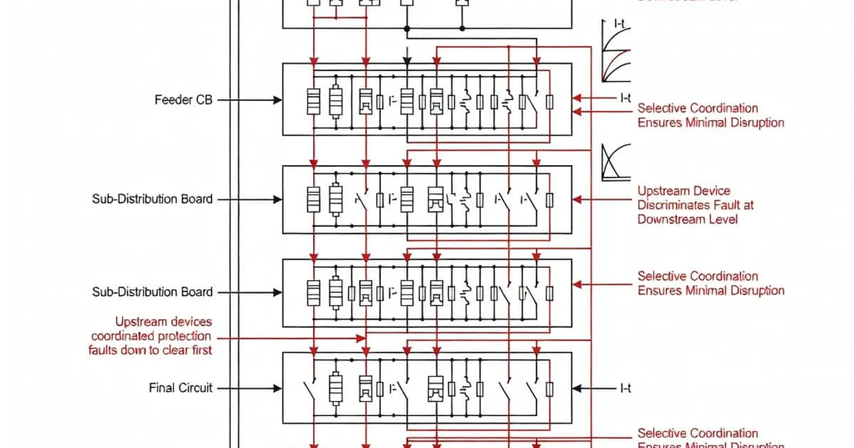
Example of Selectivity Hierarchy in a Radial System
Consider a simple radial distribution board supplied by a transformer. The main incomer feeds a busbar, which supplies several outgoing feeders, each feeding a subdistribution board or final circuit group. In a coordinated design, the downstream final circuit breaker trips first for a circuit fault, the feeder breaker trips only for feeder faults, and the incomer remains closed unless the fault is severe or located upstream of the feeder device.
This hierarchy is most effective when the following conditions are met:
- The prospective fault current at the downstream point is within the downstream device’s interrupting capacity
- The upstream device has a higher trip threshold or intentional delay
- The assembly busbar and device mounting system are verified for the available short-circuit withstand current
- The device manufacturer’s selectivity tables confirm the intended coordination pair
Without these conditions, the system may still be safe, but it will not be selective. Safety and selectivity are related, but they are not identical goals.
Practical Guidance for Panel Builders and Specifiers
For panel builders working to IEC 61439, the best practice is to treat selectivity as a documented design requirement from the outset. That means selecting protective devices early, not after the panel layout is finished. It also means confirming thermal performance and short-circuit ratings together with coordination behavior.
For specifiers, the key step is to require evidence. Ask for coordination tables, settings schedules, and short-circuit calculations. If the installation is mission-critical, request manufacturer-tested discrimination combinations rather than relying on generic assumptions.
For consultants and contractors, coordination should be reviewed at each level of the distribution system: source, main switchboard, sub-main, and final circuits. The result should be a network where faults are isolated locally, protective devices operate in the intended sequence, and the assembly remains compliant with the verified IEC 61439 design.
Conclusion
Selectivity and discrimination are not optional refinements in LV distribution; they are essential features of a well-engineered installation. IEC 61439 provides the assembly framework, but the discrimination performance comes from correct device selection, verified coordination data, and properly documented settings. In modern low-voltage systems, especially those serving critical loads, the difference between selective and non-selective protection is the difference between a local fault and a major outage.
By combining IEC 61439 assembly verification with coordinated protection design under the relevant product standards, engineers can build LV panels that are safe, reliable, and operationally resilient.
References and Further Reading
- ABB technical document on IEC 61439 and LV assembly requirements
- Schneider Electric: What IEC 61439-1 and 61439-2 mean for LV equipment specifications
- Introduction to IEC 61439
- IEC 61439-4 sample document
- Legrand white paper on assembly construction and certification
- Hager guide to IEC 61439 standards
- IEC 61439-1 overview and guidance
- GT Engineering: IEC 61439 technical standards overview
Related Panel Types
Primary power distribution from transformer to sub-circuits. Rated up to 6300A. Houses main incoming breaker, bus-section, and outgoing feeders.
High-capacity power distribution for industrial facilities. Controls and distributes incoming power to MCC, APFC, and downstream loads.
Related Components
Frequently Asked Questions
Ready to Engineer Your Next Panel?
Our team of electrical engineers is ready to design, build, and deliver your custom panel solution — fully compliant with international standards.