Generator Synchronization and Paralleling Guide
Implementing generator paralleling and load sharing systems.
Generator Synchronization and Paralleling Guide
Generator synchronization and paralleling is the process of connecting two or more generator sets, or a generator set and a utility source, onto a common low-voltage bus so they can operate as one coordinated power system. In practice, the system must match phase sequence, voltage, and frequency before the breaker closes, then continuously manage load sharing, protection, and metering after connection. For low-voltage assemblies, the enclosure, busbar system, protective devices, and control equipment must be designed and verified under IEC 61439, while the switching and protection devices typically comply with IEC 60947. As emphasized in IEC 61439, the assembly manufacturer is responsible for a verified design, not just for mechanical construction.
This matters because paralleling panels operate under demanding electrical and thermal conditions. They must tolerate starting and stopping transients, fault currents, harmonic distortion, and changing load profiles without violating temperature-rise limits, dielectric clearances, or short-circuit withstand requirements. In modern LV generator switchboards, synchronization functions are usually integrated with digital controllers, multifunction meters, protective relays, and circuit breakers housed in compartmentalized forms such as Form 3b or Form 4. These assemblies are typically built as IEC 61439-2 power switchgear and controlgear assemblies.
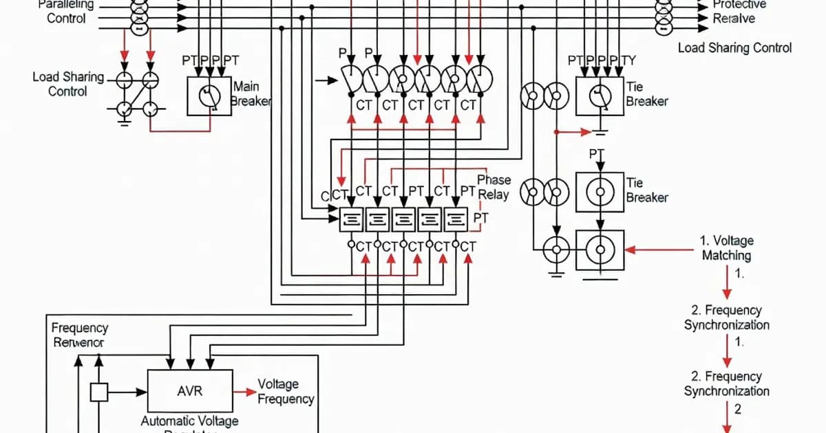
What Synchronization and Paralleling Actually Do
Synchronization ensures that the incoming generator and the live bus are aligned before closing the breaker. The controller compares phase angle, frequency, and voltage, and only permits closure when the difference is within the configured window. Paralleling then allows multiple generator sets to share real and reactive load across a common bus. In a utility-parallel system, the same principles apply, but the switchboard must also manage import/export, anti-islanding logic, utility protection, and system-level interlocking.
From a panel design standpoint, the synchronization section is not just a control cabinet. It is part of a verified low-voltage assembly that must withstand the same electrical stresses as the main distribution board. Per IEC 61439-1, the assembly must be verified for temperature rise, short-circuit withstand, dielectric properties, and protective circuit integrity. If the panel includes several incoming generator feeders, a bus-tie, and outgoing distribution sections, each functional unit must be coordinated as part of the overall design verification strategy.
Typical Applications
- Hospital and data center standby power, where N+1 generator redundancy and seamless transfer are required.
- Prime power microgrids, where generators run continuously and share load with renewable sources or the utility.
- Industrial plants, where multiple large gensets are paralleled to support process loads and motor starting.
- Marine and offshore systems, where compact, high-reliability switchboards manage severe load variation.
- Temporary power systems, where synchronized sets provide scalable capacity on construction or event sites.
IEC 61439 Requirements for Paralleling Panels
The governing framework for LV paralleling assemblies is the IEC 61439 series. IEC 61439-1 defines general rules, terms, design verification methods, and the responsibilities of the specifier, original manufacturer, and assembly manufacturer. IEC 61439-2 applies specifically to power switchgear and controlgear assemblies, which is the category used for generator paralleling switchboards. The standard replaced the older TTA/PTTA concepts with the concept of a verified assembly, meaning the panel must be proven by test, comparison, calculation, or a combination of these methods.
According to IEC 61439-1 and industry guidance from ABB and Schneider Electric, the most critical verification elements for generator synchronizing and paralleling panels are temperature rise, short-circuit withstand, dielectric properties, protective circuit continuity, clearances and creepage distances, and mechanical operation of switching devices. As documented in ABB’s IEC 61439 guides and Schneider Electric’s technical explanation of the standard, the point is not merely to select a compliant breaker or meter; the entire assembly must be verified as a system.
| Standard | Relevance to Generator Synchronization and Paralleling |
|---|---|
| IEC 61439-1 | General rules for LV assemblies; design verification, responsibilities, temperature rise, dielectric and short-circuit performance. |
| IEC 61439-2 | Specific requirements for power switchgear and controlgear assemblies such as generator paralleling boards. |
| IEC 60947-1/2 | Requirements for circuit breakers used as incomers, generator feeders, and bus couplers. |
| IEC 60529 | Ingress protection ratings for enclosure and compartment sealing, commonly IP30 to IP55 depending on design. |
| IEC 61641 | Internal arc testing for busbar and functional-unit compartments where arc containment is specified. |
Core Electrical Ratings and Design Limits
Generator paralleling panels are built within the LV definition of IEC 61439: rated operational voltage up to 1000 V AC or 1500 V DC. For three-phase systems, voltage is measured phase-to-phase. The assembly must also be assigned a rated impulse withstand voltage, or Uimp, equal to or greater than the transient overvoltage level expected in the installation. Where clearance values are above the applicable minimums, impulse withstand may be verified by test.
Short-circuit capability is especially important in paralleling systems because multiple generators can contribute fault current through a common bus. Research and manufacturer documentation show practical short-circuit withstand levels in the range of 35 kA to 65 kA for 1 second in many LV designs, with high-end industrial systems reaching even higher values depending on construction. In breaker-based incomer and feeder sections, IEC 60947-1/2 devices are typically selected so that breaking capacity, short-time withstand, and service continuity are aligned. For generator paralleling duty, low-loss air circuit breakers are often preferred because they reduce heat dissipation while offering high switching endurance and adjustable protection settings.
Neutral sizing must also be addressed carefully. Per IEC 61439 guidance summarized in the research, the neutral conductor cross-section is generally 100% of the phase conductor up to 16 mm², and 50% above 16 mm², with a minimum of 16 mm², unless the design requires a larger conductor because of harmonics, unbalanced loading, or non-copper conductors. This is particularly important in generator systems supplying nonlinear loads such as UPS systems, VFDs, LED lighting, and IT equipment, where neutral currents can exceed expectations.
Temperature Rise and Load Sharing Considerations
Temperature-rise verification is one of the most important design checks in generator synchronizing panels. Paralleling switchboards often contain multiple incomers, synchronizing controllers, meters, protection relays, terminal wiring, and dense busbar arrangements, all of which contribute to heat buildup. Per IEC 61439 verification principles, temperature-rise assessment can be based on testing, comparison with a reference design, or calculation methods, but only under defined conditions. The research notes that calculation-based verification for assemblies up to 1600 A may be used in certain multi-compartment constructions when matched to similar tested assemblies that share functional unit groups, construction type, dimensions, internal separation, power losses, and outgoing circuit arrangements.
Testing is typically performed at an average ambient temperature not exceeding 35°C. The rated diversity factor, or RDF, becomes a key planning parameter because not every outgoing circuit is expected to carry full load simultaneously. However, paralleling systems demand conservative assumptions because generator load sharing depends on accurate current measurement, governor response, and voltage regulation. If one generator is overloaded or underloaded, the entire parallel group can suffer frequency instability, circulating current, or nuisance tripping.
For this reason, design engineers should coordinate the panel thermal model with the actual control strategy. In systems with multiple gensets, a common approach is to use controllers that manage kW sharing through speed governor control and kVAr sharing through voltage regulator droop or cross-current compensation. Proper load sharing reduces the risk of one machine running hotter than the others and supports stable operation during step changes in load.
Protection, Metering, and Synchronizing Instruments
A generator paralleling panel needs more than on/off controls. It requires protective relays, synchronizing logic, multifunction metering, and often event recording. Modern designs use four-quadrant power meters with graphical displays that can measure A, V, power factor, frequency, kW, kVA, kVAr, energy, demand, and total harmonic distortion, often up to the 31st harmonic. Some meters also capture waveforms during synchronization events, making them useful for commissioning and troubleshooting.
These functions are not cosmetic. They support breaker closing permissives, load sharing diagnostics, and power quality analysis. For example, if the synchronization window is too narrow, the breaker may fail to close under unstable utility conditions. If the window is too wide, closure can produce a damaging transient torque shock on the generator shaft and a large inrush on the bus. If harmonic distortion is excessive, the panel may show false power factor readings or overheating in neutral conductors and transformers.
Protection settings generally include under/overvoltage, under/overfrequency, reverse power, overcurrent, earth fault, and sometimes negative sequence protection. In utility-parallel installations, additional anti-islanding, import/export limit, and utility-reclose coordination functions are required. The protection system should be coordinated with the breaker characteristics, transformer impedances, and overall arc-flash strategy of the installation.
Short-Circuit Withstand and Internal Arc Performance
A generator paralleling switchboard must withstand not only normal operating current but also fault energy. IEC 61439 requires verification of short-circuit withstand for the assembly, including busbars, supports, terminals, and protective device interfaces. In practical industrial systems, internal ratings such as Icw, Icu, and Ics may be specified at 35 kA, 50 kA, 65 kA, or even 150 kA depending on the platform and breaker class. In some documented designs, Icu, Ics, and Icw are aligned for the main incomers and feeders to simplify coordination and ensure predictable performance.
Internal arc withstand is increasingly specified for high-availability installations. The research identifies IEC 61641 testing at 65 kA for 0.4 seconds in busbar chambers and functional units. This is a critical feature where operators may need to access adjacent compartments or where the switchboard is installed in occupied electrical rooms. Arc containment does not eliminate the need for proper protection coordination, but it reduces the severity of an internal fault and improves personnel safety.
Internal arc performance is closely related to compartment design. Assemblies built in Form 3b or Form 4 separation reduce the chance that a fault in one functional unit propagates into another. Vertical cable alleys, segregated busbar chambers, and properly rated door latches all contribute to the final behavior of the board under fault conditions. The enclosure IP rating should remain effective after verification tests, and the assembly should not rely on ad hoc barriers or untested modifications.
Enclosure Construction, Separation Forms, and IP Rating
Generator synchronization panels are often specified with a high degree of segregation to improve maintainability and fault containment. Form 3b and Form 4 configurations are common because they separate busbars, functional units, and cable terminations into distinct compartments. This allows one outgoing feeder or generator breaker to be serviced with reduced risk to the rest of the system. It also improves resistance to fault propagation and supports clearer cable management for large paralleling systems.
Ingress protection typically ranges from IP30 to IP55 depending on the site environment, ventilation strategy, and door sealing design. Higher IP ratings are often selected for harsh industrial environments, coastal locations, or installations with dust and humidity exposure. However, the enclosure must still allow the thermal performance needed by the switchgear and controllers. Good engineering balances sealing, airflow, accessibility, and heat dissipation.
Mechanical robustness and clear labeling are also essential. The panel should include permanent danger notices, circuit identification, and arc-flash warning signage where required by the site safety program. Because paralleling boards are operated by maintenance technicians and commissioning engineers, layout clarity reduces human error during breaker testing, controller parameterization, and source transfer operations.
Manufacturer Responsibilities and Verification Workflow
IEC 61439 assigns clear roles. The specifier defines the system requirements, such as voltage, fault level, IP rating, separation form, and service conditions. The original manufacturer designs the assembly platform and performs the design verification. The assembly manufacturer then builds the actual panel according to the verified design and the original manufacturer’s instructions. This distinction is important in paralleling projects because custom bus arrangements, generator protection schemes, and controller integration often create unique configurations.
Industry guidance from ABB, Schneider Electric, and Hager emphasizes that verification should be based on the closest tested design wherever possible. In other words, if a synchronization panel is built from a proven platform, the design should match the tested reference in functional unit groupings, dimensions, power losses, internal separations, and cable arrangements. This approach is more defensible than relying on unbounded “equivalent” assumptions.
The practical consequence is that project teams should collect complete technical data before fabrication: generator short-circuit contribution, transformer impedance, load profiles, ambient conditions, future expansion allowances, and controller communication requirements. The more accurately these are defined, the easier it is to produce a compliant and maintainable assembly.
Specification Table for a Typical LV Generator Paralleling Panel
| Parameter | Typical Range or Requirement | Design Note |
|---|---|---|
| Rated operational voltage | Up to 1000 V AC | LV assemblies under IEC 61439-1. |
| Rated impulse withstand voltage | As required by system transient level | Verify against clearances and overvoltage category. |
| Short-circuit withstand | 35 kA to 65 kA for 1 s, or higher by platform | Coordinate busbars, breakers, and supports. |
| Protection device standard | IEC 60947-1/2 | Commonly air circuit breakers for incomers and bus couplers. |
| Ingress protection | IP30 to IP55 | Selected based on site environment and cooling method. |
| Internal arc performance | Up to 65 kA / 0.4 s in tested systems | Particularly valuable in occupied electrical rooms. |
| Metering | A, V, Hz, kW, kVA, kVAr, PF, THD, energy | Supports synchronization and load sharing diagnostics. |
| Neutral conductor sizing | 100% up to 16 mm²; 50% above 16 mm², min. 16 mm² | Increase size if harmonics or imbalance warrant it. |
Examples of Commercial LV Platforms Used for Paralleling
Major manufacturers offer IEC 61439-compliant LV platforms suitable for generator synchronization and paralleling. Siemens Sivacon S8 is commonly used for high-current applications and can be configured in Form 4 with high short-circuit ratings. ABB’s UniGear family and associated low-voltage solutions are widely used for industrial power distribution and generator control with protection relays and metering integration. Schneider Electric’s Okken and BlokSeT platforms are designed for high-performance power distribution and can be equipped with PowerLogic metering and generator control interfaces. Eaton’s Power Xpert UX and xEnergy systems are also used in generator-driven installations where modularity and maintenance access are priorities. Hager and other suppliers provide guidance and modular solutions for structured low-voltage assemblies.
These product families demonstrate a common pattern: the generator control function is integrated into a verified switchboard architecture rather than treated as a separate control panel. This is the correct engineering approach because the synchronization logic, protective devices, metering, busbar system, and enclosure all interact electrically and thermally.
Best Practices for Design, Commissioning, and Operation
- Use tested platforms whenever possible. Match the final design to a verified reference assembly instead of reinventing the busbar or compartment structure.
- Define the load-sharing philosophy early. Decide whether the system will use isochronous load sharing, droop control, or mixed modes for utility parallel operation.
- Specify adequate metering. Include multifunction meters with waveform capture and harmonic analysis to support commissioning and troubleshooting.
- Coordinate protection and breaker settings. Align generator, bus coupler, and outgoing feeder protection to avoid nuisance trips and to maintain selectivity.
- Plan thermal margins conservatively. Account for cabinet losses, ambient temperature, diversity, and future expansion.
- Use compartmentalization. Form 3b or Form 4 layouts improve maintainability and fault containment.
- Verify neutral and earthing conductors. Nonlinear loads can increase neutral current and heating substantially.
- Document all control functions. Synchronizing permissives, breaker interlocks, and emergency stop logic should be fully recorded in the project documentation.
Related Panel Types
Related Components
Frequently Asked Questions
Ready to Engineer Your Next Panel?
Our team of electrical engineers is ready to design, build, and deliver your custom panel solution — fully compliant with international standards.