IoT-Connected Panels and Industry 4.0
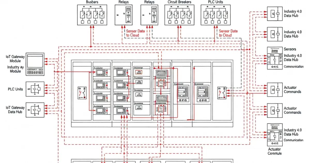
Connecting panels to cloud and IIoT platforms.
IoT-Connected Panels and Industry 4.0
IoT-connected low-voltage panels are moving from passive power distribution into active digital assets. In an Industry 4.0 environment, the panel is no longer only a place where feeders, protection devices, and control circuits are assembled. It also becomes a node for condition monitoring, energy analytics, remote diagnostics, and predictive maintenance. That shift creates clear technical opportunities, but it also raises the bar for design verification, enclosure performance, EMC behavior, and cybersecurity.
For IEC 61439 compliant assemblies, the fundamental requirement does not change: the assembly must be a verified assembly with responsibilities split between the original manufacturer and the assembly manufacturer. Per IEC 61439-1, the original manufacturer establishes the design and its verification, while the assembly manufacturer is responsible for building the final panel in accordance with that verified design and ensuring conformity before delivery. This distinction is critical when IoT gateways, edge controllers, wireless modules, or additional communication cabling are added to a panel design.[1][3][4]
In practice, IoT integration should never compromise the core electrical characteristics of the assembly. Clearances, creepage distances, power-frequency withstand, impulse withstand, temperature rise, and short-circuit withstand still govern the panel. As documented in IEC 61439-1 Clause 10, these requirements remain mandatory whether the panel is purely electromechanical or digitally connected to a cloud platform.[2][3][6]
How IEC 61439 Applies to IoT-Enabled Panels
IEC 61439 series governs low-voltage switchgear and controlgear assemblies with rated voltages up to 1000 V AC or 1500 V DC. The standard replaced the earlier IEC 60439 framework and introduced a stronger emphasis on verifiable design rules rather than legacy type-tested concepts.[1][4] For IoT-connected panels, this matters because additional electronics introduce heat, wiring density, and EMC exposure that can invalidate assumptions if they are not covered by the verified design.
The latest editions remain the key reference set: IEC 61439-1:2020 for general rules, IEC 61439-2:2011 for power switchgear and controlgear assemblies, and IEC 61439-3:2024 for distribution boards intended for ordinary persons.[6] A digital panel that includes IoT modules is still an LV assembly first and a smart system second. Its compliance must be assessed under the same verification framework as any other assembly.
There are no direct “IoT clauses” in IEC 61439 as of the 2024 editions, but connectivity affects several required verifications. The most important are thermal behavior, insulation coordination, EMC performance, and protection against ingress. In other words, the standard does not regulate the cloud connection itself; it regulates whether the panel remains safe and functional after the connected equipment is installed.[3][4]
Verification Requirements That Matter Most for Industry 4.0
Digital equipment installed in an assembly changes the design balance. Even a compact IoT gateway adds dissipation, cable density, and possible hotspots. A cellular modem or Ethernet switch may also require a different enclosure layout, more careful segregation, or improved shielding. IEC 61439 requires that these changes be evaluated through design verification, not treated as minor accessories.
Temperature rise verification
Temperature rise is one of the most important limits for connected panels. IEC 61439-1 Clause 10.10 covers temperature rise verification. For many multi-compartment designs, verification by calculation is limited to assemblies up to 1600 A under defined conditions, and the assumptions must remain valid for the same functional units, dimensions, and power losses.[3] The standard’s ambient reference is typically 35°C average surrounding air, and the final temperature rise must remain within acceptable limits for conductors, terminals, devices, and electronic modules.
This is especially important for IoT retrofits. A gateway, managed switch, remote I/O module, or power supply can add continuous heat load even when the main power circuit is lightly loaded. If that added dissipation pushes terminal temperatures beyond the verified design, the assembly is no longer equivalent to the original verification basis. In practice, designers should map heat sources, maintain airflow paths, and avoid clustering communication electronics directly above high-loss devices such as VFDs or compact molded-case circuit breakers.
Short-circuit withstand
Clause 10.11 addresses short-circuit withstand capability. For Industry 4.0 installations, this is not just about protecting equipment from fault currents. It is also about preserving uptime for digital systems that depend on the panel for monitoring, data collection, and remote operation.[3][8] A fault that damages communication modules or auxiliary control circuits can interrupt monitoring across an entire process line, even if the main power path remains intact.
Where IoT functions are essential to operations, short-circuit withstand should be verified with the same discipline as busbar and feeder protection. The panel must tolerate prospective fault current, maintain segregation where required, and ensure that a single fault does not cascade into loss of connected control infrastructure.
Dielectric properties and insulation coordination
Clause 10.9 covers dielectric properties, including power-frequency withstand and impulse withstand. This remains relevant for panels hosting Ethernet gateways, industrial routers, DC power supplies, and communication interfaces, because these devices often introduce additional terminals and internal circuits into the assembly.[2][3] Proper clearance and creepage distances must be maintained, especially where higher pollution levels, condensation risk, or mixed-voltage wiring are present.
Industry 4.0 projects frequently mix low-energy electronics with traditional power equipment in the same enclosure. That makes insulation coordination more important, not less. Designers should ensure that auxiliary power rails, sensor wiring, and communications cabling are separated from power conductors in a manner consistent with the verified design and the expected overvoltage category.
Degree of protection and enclosure suitability
IEC 61439 cross-references IEC 60529 for enclosure protection degree. For connected panels, the enclosure rating must match the installation environment and the communication architecture. In many indoor applications, IP30 to IP43 is common, while more robust industrial enclosures may require higher ratings depending on dust, water exposure, and cleaning procedures.[5] Where outdoor operation or harsh environments are involved, designers may need to move toward IP54 or higher, while also ensuring that cable entries and ventilation arrangements do not reduce the effective rating.
As shown in manufacturer guidance from Hager and ABB, the correct IP degree must be selected in conjunction with thermal and mechanical requirements, not as a standalone decision.[2][5][9] A high IP enclosure with poor thermal management can create overheating. A ventilated enclosure with inadequate filtration can compromise electronics. Smart panels require both protection and heat control.
Standards and Related Documents
IEC 61439 is the core standard, but IoT-connected panels usually depend on several related documents to achieve a workable design.
- IEC 61439-1:2020 — General rules, definitions, and verification methods for low-voltage assemblies.[6]
- IEC 61439-2:2011 — Power switchgear and controlgear assemblies, including typical forms of internal separation and verification expectations.[2][9]
- IEC 61439-3:2024 — Distribution boards intended for ordinary persons, often relevant for compact connected sub-distribution boards.[6]
- IEC 60529 — Degrees of protection provided by enclosures, used for IP rating selection.[5][9]
- IEC 60947 series — Low-voltage switchgear and controlgear devices such as contactors, switch-disconnectors, and protective devices frequently used inside smart panels.[1]
- IEC 62443 — Industrial cybersecurity framework often applied to IIoT networks and remote-access architectures, though not part of IEC 61439 itself.
Because IEC 61439 does not define cybersecurity requirements, security must be addressed as a system-level design issue. In practice, that means network segmentation, hardened access control, secure remote connectivity, and patch management for gateways and embedded controllers. The panel can be mechanically and electrically compliant while still being vulnerable at the software and network layer if cybersecurity is ignored.
Specification Table for IoT-Connected Panels
| Design Aspect | Typical Requirement | IEC / Guidance Reference | Industry 4.0 Impact |
|---|---|---|---|
| Rated voltage | Up to 1000 V AC or 1500 V DC | IEC 61439 series | Defines the base low-voltage assembly scope |
| Temperature rise | Verify by test, comparison, or calculation; 35°C ambient basis common | IEC 61439-1 Clause 10.10 | IoT electronics add heat and may require layout changes |
| Short-circuit withstand | Icw and related withstand capability must be verified | IEC 61439-1 Clause 10.11 | Prevents loss of connected monitoring and control functions |
| Dielectric performance | Power-frequency and impulse withstand verification | IEC 61439-1 Clause 10.9 | Important when adding auxiliary electronics and mixed-voltage circuits |
| Ingress protection | Commonly IP30 to IP43 for indoor modular panels; higher for harsh sites | IEC 60529, referenced by IEC 61439 | Protects gateways, sensors, and communication hardware |
| Internal separation | Forms 1 to 4b depending on application and maintenance strategy | IEC 61439-2 | Supports segregation of power and digital control compartments |
| Cybersecurity | Segmentation, access control, secure remote access | IEC 62443 good practice | Protects IIoT data paths and remote maintenance interfaces |
Design Strategy for Connected Panels
The most robust IoT-connected panels are designed as verified modular systems rather than ad hoc retrofits. As explained in manufacturer guidance from ABB and Schneider Electric, the safest route is to start with an original manufacturer platform and extend it only within the verified design envelope.[2][4][9] This is especially important when the panel must support remote diagnostics, energy metering, or condition monitoring in a production environment.
Use modular verified architectures
Modular architectures allow the designer to preserve established thermal and short-circuit characteristics while adding communication hardware in designated compartments. Internal separation forms such as Form 2b, 3b, or 4a/4b can help segregate power circuits from sensitive digital electronics, reducing both electrical risk and maintenance disruption.[8] Where the design is based on a manufacturer’s tested platform, additional modules can often be integrated with less engineering uncertainty than a fully custom layout.
Plan for airflow and power loss
Digital devices may be small, but they are not thermally insignificant. Ethernet switches, 24 VDC power supplies, industrial routers, and data loggers can generate concentrated losses that matter in compact enclosures. If the panel uses natural ventilation, those losses should be included in the overall heat balance. If forced ventilation is used, filter maintenance and fan reliability become part of the asset management strategy.
For assemblies above the range where calculation is safely applicable, or where the configuration is highly complex, verification by test is the stronger choice. Industry sources note that design assumptions become less robust as panel size, diversity of loads, and degree of customization increase.[3]
Separate power and communication layers
Good connected-panel design separates high-energy power conductors from communication circuits. Use dedicated wiring ducts, shielded cables where appropriate, and clearly segregated terminal zones. Maintain physical separation for Ethernet, fieldbus, and sensor wiring so that electromagnetic interference does not degrade signal integrity. This is particularly important when frequency converters, soft starters, or contactor banks share the same enclosure.
Where wireless communication is used, the enclosure must also be evaluated for RF attenuation, antenna placement, and EMC impact. A metal enclosure can suppress wireless signals if the antenna is placed poorly. That problem is often solved by using external antenna mounts or controlled RF exit points without compromising the enclosure rating.
Product and Platform Examples
Major manufacturers already support the move toward digitally enabled LV assemblies, even when the exact IoT layer is implemented through add-on modules rather than a dedicated “smart panel” label.
| Manufacturer | Example Platform | Compliance Focus | Industry 4.0 Capability |
|---|---|---|---|
| ABB | SACE Tmax XT assemblies | IEC 61439-1/-2, high Icw ratings, IP31–IP54 options | Cloud-connected condition monitoring through ABB digital ecosystems |
| Schneider Electric | Verified low-voltage assemblies | Temperature rise and construction verification under IEC 61439 | EcoStruxure-based data integration and energy analytics |
| Hager | LVMSB / LVMDB / SDB platforms | IEC 61439 verified boards, IP30–IP43, Icw around 35 kA in common ranges | Modular platforms suitable for gateway and monitoring integration |
| Siemens | LV panel systems | Form-based internal separation and verified system approach | Digital monitoring and configuration workflows for connected power distribution |
| Lauritz Knudsen | LV IEC panels | Full IEC 61439 verification approach | Suitable for distribution modernization and connected metering architectures |
These examples illustrate a common pattern: the manufacturer provides the verified electrical architecture, while the digital ecosystem is layered on top through gateways, monitoring modules, and software platforms. The panel remains IEC 61439 compliant only if those additions stay within the verified design rules and do not degrade the assembly’s essential ratings.[1][2][5][7][9]
Common Mistakes in IoT Retrofit Projects
Many retrofit projects fail because the digital objective is defined before the electrical constraints are understood. That sequence leads to ad hoc drilling, overcrowded wiring ducts, hidden thermal bottlenecks, and unverified changes to enclosure behavior.
- Adding a gateway without revisiting thermal verification — even a small device can create a hot spot in a dense enclosure.
- Ignoring short-circuit implications — communication hardware must be protected from fault energy and coordination issues.
- Mixing power and data wiring — this increases EMC risk and complicates maintenance.
- Assuming IP rating is unchanged after modification — cable glands, vents, and accessories can reduce ingress protection.
- Leaving cybersecurity outside the design review — remote access must be secured from the start.
- Using non-verified extensions — changes outside the original manufacturer’s verified system can compromise conformity.[3][4][8]
Best Practices for Industry 4.0 Panel Design
To build a reliable IoT-connected panel, begin with the verification structure and then add digital functionality in a controlled way.
- Start with an original manufacturer system and use verified accessories and extensions wherever possible.
- Model all power losses, including PLCs, routers, switches, gateways, and auxiliary power supplies.
- Keep ambient assumptions realistic; the 35°C reference used in many IEC 61439 verifications should be checked against the actual installation site.[3]
- Choose the correct internal separation form to isolate maintenance zones and digital components.[8]
- Use shielded and segregated cabling for communication and sensor circuits.
- Verify enclosure ratings after modifications, especially where vents, displays, or antenna ports are added.
- Plan cybersecurity as part of the architecture using segmented networks and secure remote access principles aligned with IEC 62443.
- Document the as-built configuration so service teams know which modules were installed and which verification basis applies.
Industry experience shows that many legacy panels were built before the current IEC 61439 framework became standard practice. That means modernization projects often need a careful compliance review before connectivity is added.[4] In many cases, the safest path is not to modify the existing panel in place, but to replace it with a modular verified assembly that is already designed for digital expansion.
Conclusion
IoT-connected panels are a natural part of Industry 4.0, but they must be engineered within the discipline of IEC 61439
Related Components
Frequently Asked Questions
Ready to Engineer Your Next Panel?
Our team of electrical engineers is ready to design, build, and deliver your custom panel solution — fully compliant with international standards.