Power Factor Correction Panel Design and Sizing
Designing and sizing APFC panels for optimal reactive power compensation.
Power Factor Correction Panel Design and Sizing
Power factor correction panel design is not simply a matter of adding capacitor steps to a distribution board. An IEC 61439-compliant automatic power factor correction (APFC) panel must be engineered as a complete low-voltage assembly, with verified thermal performance, short-circuit withstand capability, adequate conductor sizing, safe switching arrangements, and documented conformity for the final installation. In practice, this means combining the assembly requirements of IEC 61439-1 and IEC 61439-2 with the component requirements of IEC/EN 60831 for capacitors, IEC 60947 for switching and protection devices, and IEC 60529 for enclosure protection. As documented in IEC 61439 guidance, the manufacturer is responsible for proving the assembly is fit for service, not just selecting good-quality parts.
For APFC systems, this compliance framework matters because capacitor banks operate continuously, switch frequently, and generate heat and transient currents that can stress the panel if the design is undersized. A properly sized panel improves energy efficiency, reduces utility penalties, and stabilizes voltage, while a poorly designed one can suffer nuisance tripping, capacitor failure, excessive harmonics, and accelerated thermal aging.
Relevant IEC Standards and References
Primary assembly standards
IEC 61439 governs low-voltage switchgear and controlgear assemblies up to 1,000 V AC or 1,500 V DC. IEC 61439-1 sets the general rules for design verification, temperature rise, dielectric performance, clearances, creepage distances, protection against electric shock, and mechanical strength. IEC 61439-2 applies to power switchgear and controlgear assemblies, which is the relevant part for APFC distribution panels used in commercial and industrial power systems. These standards require the assembly manufacturer to demonstrate compliance by test, comparison with a verified reference design, or calculation where permitted.
One important change from the older IEC 60439 series is the clearer separation of responsibilities between the original manufacturer and the assembly manufacturer. The original manufacturer establishes the verified design platform, while the assembly manufacturer ensures the actual build conforms to that verified design. This distinction is especially important for APFC panels because component substitution, step changes, and cabinet resizing can materially affect losses and temperature rise.
Component-specific standards
Capacitors used in APFC panels should comply with IEC/EN 60831-1 and IEC/EN 60831-2. Typical capacitor requirements include a rated insulation voltage of 690 V AC, a voltage rating of 1.1 times Un, and capacitance tolerance of −5% to +10%. Standard frequency is 50 Hz, with 60 Hz versions available for specific applications. IEC/EN 61921 covers power factor correction equipment requirements at the system level, while IEC 60947-2 governs circuit-breakers and IEC 60529 defines enclosure ingress protection ratings.
These standards are complementary. IEC 60831 ensures the capacitor itself is suitable for continuous reactive duty, while IEC 61439 ensures the complete panel behaves safely as an assembly under actual operating conditions.
Key Technical Specifications for APFC Panel Design
Reactive power calculation and sizing
The starting point for APFC sizing is the reactive power required to raise the power factor from an existing value to the target value. The standard sizing expression is:
kvarPFC = kWLoad × (tan φ1 − tan φ2) = kWLoad × M
Where φ1 is the initial power factor angle, φ2 is the desired power factor angle, and M is the multiplication factor taken from power factor correction tables. This formula is widely used in capacitor bank selection and remains the practical basis for panel sizing.
For example, a 1,000 kW plant operating at 0.71 power factor and corrected to 0.97 requires approximately 740 kvar of correction. The correction factor M in that case is 0.74. In real installations, engineers often round the installed kvar slightly upward to account for load variation, future expansion, and reduced capacitor ageing margin over time.
It is also good practice to avoid overcorrection. If the plant load varies significantly, a fixed capacitor bank can drive the power factor leading, causing voltage rise and possible penalty from the utility. This is why automatic stepped correction is preferred in dynamic industrial loads.
Frequency and operating conditions
IEC 61439 requires the assembly to be designed for its rated frequency. Standard APFC panels operate at 50 Hz, and acceptable service frequency range is generally 98% to 102% of rated frequency, or 48.5 Hz to 51 Hz for a 50 Hz system. If the system operates at 60 Hz, all component ratings, particularly capacitor current and switching characteristics, must be confirmed accordingly. Conventional 50 Hz switching devices do not automatically provide equal performance at other frequencies, and special devices may be required for DC or very low frequency applications.
Temperature rise and thermal loading
Temperature rise verification is one of the most important aspects of APFC panel design under IEC 61439. The standard requires that the assembly be verified for thermal performance under worst-case loading, with covers, partitions, and functional units installed as in normal service. For multiple-compartment assemblies, verification by calculation is permitted only up to a rated current of 1,600 A, subject to the standard’s conditions. The accepted ambient temperature reference for testing is 35 °C.
This matters because capacitor banks and switching devices dissipate heat continuously. Typical losses come from capacitor dielectric loss, contact resistance in contactors or thyristor switches, fuse dissipation, and busbar losses. If the design does not account for these losses, the internal temperature can exceed the capacitor’s permissible operating range, reducing life and triggering protective devices.
Rated diversity factor, or RDF, is used to reflect the fact that not all capacitor steps operate at full load simultaneously. In practice, RDF helps avoid overestimating power dissipation while still maintaining a conservative thermal design. The assembly nameplate should state the RDF used in the verification basis.
Conductor and neutral sizing
IEC 61439 provides conductor sizing guidance that directly affects APFC panel reliability. For neutral conductors, the cross-section shall be 100% of the phase conductor size for conductors between 50% and 16 mm², and 50% of the phase conductor size for conductors above 16 mm², with a minimum of 16 mm². Where non-copper conductors are used, the equivalent copper cross-section or larger must be provided.
In APFC panels, attention should also be given to internal wiring between the main busbar, protection devices, capacitor steps, and discharge resistors. Non-protected live conductor length between the main busbar and associated short-circuit protective device should not exceed 3 meters, per the guidance referenced in IEC 61439 documentation. This limitation helps reduce fault energy exposure in unfused sections.
APFC Panel Sizing Methodology
Step 1: Determine load profile
Begin by collecting the plant’s real demand data. Useful inputs include average kW, maximum kW, existing power factor, load variation by time of day, harmonic distortion, motor starting frequency, and planned future expansion. A panel sized only on connected load may be too large for a plant that rarely runs at full demand, while a panel sized too tightly may not cover production peaks.
Step 2: Calculate required kvar
Once the load profile is known, calculate the kvar necessary to shift the power factor to the target, often 0.95 to 0.99 depending on utility rules and harmonic conditions. As a practical rule, many industrial sites aim for about 0.98 lagging at the point of common coupling to avoid penalties while leaving a small margin against leading power factor.
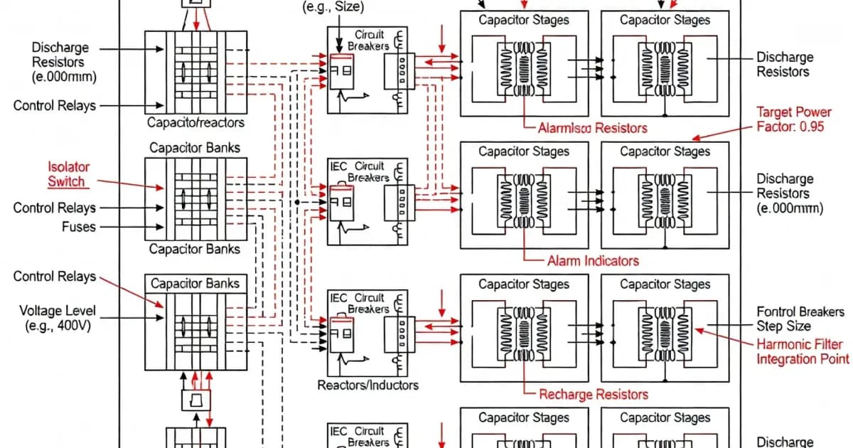
Step 3: Select step arrangement
Choose the step sequence to match load variation. A common arrangement is 1:1:1:1 across four steps or a mixed binary sequence such as 1:1:2:2:4 for finer control. The right sequence depends on how often the load changes and how close the corrected power factor must stay to target. More steps give better regulation but increase component count, panel size, and heat dissipation.
Step 4: Verify capacitor and switching device ratings
Each capacitor step must be rated for its kvar, voltage, and current. Capacitor units commonly appear in 450 V, 550 V, and higher ratings depending on system conditions. Switching devices must be suitable for capacitor duty, because inrush currents during energization can be very high. In properly designed APFC panels, detuned reactors or pre-insertion devices may be used to limit harmonics and switching stress where the supply network contains distortion.
Step 5: Size protection and busbars
Protection devices must handle both steady-state current and fault current. The panel’s busbar system must be rated for the prospective short-circuit current at the installation point, and the conditional rated short-circuit current must be declared on the nameplate. Selection of NH fuse bases or circuit-breakers should account for power dissipation, because even small losses add up across multiple feeder ways and can materially affect internal temperature rise.
Specification and Comparison Table
| Item | Typical Requirement or Value | Design Significance |
|---|---|---|
| Assembly standard | IEC 61439-1 / IEC 61439-2 | Defines verification, ratings, and conformity for the complete panel |
| Capacitor standard | IEC/EN 60831-1 / 60831-2 | Sets voltage, tolerance, and performance limits for capacitor units |
| Standard ambient for verification | 35 °C | Basis for temperature rise assessment |
| Capacitor insulation voltage | 690 V AC typical | Supports operation in low-voltage industrial systems |
| Capacitance tolerance | −5% / +10% | Affects kvar output and step balancing |
| Neutral conductor sizing | 100% or 50% depending on conductor size | Ensures safe current carrying capability under IEC 61439 |
| Non-protected live conductor length | Maximum 3 m | Reduces fault exposure in unfused sections |
| Rated frequency | 50 Hz standard | Must match the supply system and component verification basis |
Verification Procedures Under IEC 61439
Design verification methods
IEC 61439 requires design verification across multiple categories rather than relying on a single test. The main verification methods are testing, comparison with a verified reference design, or calculation where the standard allows it. The verification scope includes temperature rise, dielectric properties, short-circuit withstand strength, clearances and creepage distances, protective circuit integrity, terminal arrangement, mechanical operation, degree of protection, and device installation compatibility.
In practical panel building, temperature rise testing is mandatory for the design family, even when some other verifications can be supported by calculation or reference to a tested configuration. This is particularly relevant to APFC panels because the thermal behavior of capacitor banks changes when the number of steps, internal partitions, ventilation arrangements, or protective device types changes.
Reference design and substitution rules
Where a panel is verified by reference to a tested design, the new assembly must remain within the construction envelope of that reference design. The same or reduced internal separation, equal or lower power loss in comparable sections, identical or compatible functional unit grouping, and no increase in the number of outgoing circuits per section are typical constraints. This is how IEC 61439 prevents “copy-paste” assemblies from diverging into untested configurations.
Short-circuit verification
APFC panels must be verified for the prospective short-circuit current at the installation point. The assembly marking should include the conditional rated short-circuit current, for example 70 kA, together with rated voltage, rated frequency, and RDF. This data is not decorative; it determines whether the panel can be safely installed on a given busway, transformer secondary, or main distribution board.
Short-circuit verification is especially important for capacitor banks because capacitor discharge and fault contributions can intensify current stress. Protection coordination, fuse selection, and busbar bracing must all be considered together.
Manufacturer Specifications and Product Examples
Manufacturers such as ABB, Schneider Electric, Eaton, Legrand, and Hensel Electric publish panel builder documentation and component guides that help confirm IEC 61439 compliance. Typical distribution board capacities referenced in manufacturer literature include up to 250 A for certain enclosure systems and up to 630 A for larger panelboard platforms. NH fuse bases are commonly specified with dissipation values such as 4.2 W per pole for NH 00, 4.4 W for NH 1, and 7.0 W for NH 2, which is useful when building thermal models for APFC enclosures.
Capacitor series may be offered in 450 V, 550 V, or higher ratings depending on supply conditions and harmonic environment. The actual selection must consider whether the site is lightly distorted, moderately distorted, or requires detuned or filtered correction equipment. A capacitor that is technically rated for voltage may still be unsuitable if harmonic current exceeds its thermal limit.
Design Best Practices
Environmental considerations
Ambient temperature has a direct impact on APFC panel performance. If the panel is installed in a cool, air-conditioned electrical room, its current-carrying capability may be higher than in a 35 °C verification environment, but the assembly manufacturer must still document the basis for any uprating. Conversely, if the panel is installed near process heat or poor ventilation, derating may be required.
Moisture, dust, and corrosive atmospheres also influence enclosure selection. IEC 60529 ingress protection ratings should be matched to the installation site. For indoor electrical rooms, an IP rating suitable for dust control and accidental contact is often sufficient, while harsher environments may require higher protection and filtered ventilation.
Protection and switching strategy
Capacitor duty contactors, fast-acting fuses, circuit-breakers, or thyristor switching stages should be selected according to the switching frequency and harmonic environment. Thyristor switching is often preferred where load changes are rapid and frequent, because it avoids contact wear and improves response time. Mechanical contactor switching is usually adequate for slower load variations. In either case, contactor and fuse selection must reflect the capacitor inrush current profile.
Harmonic mitigation
Where non-linear loads such as variable frequency drives, rectifiers, or UPS systems are present, the APFC panel may need detuned reactors or harmonic filter stages. This prevents resonance between capacitors and the supply system, which can otherwise magnify current and overheat the bank. In mixed-load plants, harmonic analysis should be part of the early design phase rather than a correction after commissioning.
Documentation and routine verification
An IEC 61439-compliant APFC panel should be delivered with a complete technical file, including the assembly nameplate, rated voltage, short-circuit current, frequency, RDF, design verification evidence, component declarations of conformity, and routine verification records. Routine verification confirms the actual built panel matches the intended design and that the protective measures, wiring, and function checks are correct before energization.
Industry Standards Evolution
The transition from IEC 60439 to IEC 61439 materially improved APFC panel engineering discipline. The newer series introduced clearer verification logic, expanded test requirements, and more explicit accountability for the design and assembly phases. It also formalized concepts such as rated diversity factor and improved consistency in how assemblies are rated for short-circuit performance and temperature rise. For panel builders, this means the design must be traceable, repeatable, and documented, not merely assembled from compliant parts.
For power factor correction systems, the practical effect is significant. A bank that works in service is not enough; the assembly must be provably safe under the worst credible thermal and electrical conditions. That is the central engineering requirement behind IEC 61439-compliant APFC design.
References and Further Reading
ABB guidance on IEC 61439 assembly considerations
Introduction to IEC 61439 and verification concepts
Hensel guide to IEC/EN 61439 design and application
Comar Cond power factor correction technical guide
Related Panel Types
Automatic capacitor switching for reactive power compensation. Thyristor or contactor-switched, detuned or standard configurations.
Fixed or automatic capacitor bank assemblies for bulk reactive power compensation in industrial and utility applications.
Related Components
Frequently Asked Questions
Ready to Engineer Your Next Panel?
Our team of electrical engineers is ready to design, build, and deliver your custom panel solution — fully compliant with international standards.