Complete Guide to the IEC 61439 Standard Series
Comprehensive overview of all IEC 61439 parts, their scope, and how they apply to different panel types.
Complete Guide to the IEC 61439 Standard Series
The IEC 61439 series is the international benchmark for low-voltage switchgear and controlgear assemblies. It replaced the older IEC 60439 framework and created a more rigorous, more clearly structured basis for designing, verifying, and manufacturing assemblies used in distribution, motor control, automation, and power management applications. As defined in IEC 61439-1:2020, the series sets out general rules for definitions, service conditions, construction, performance characteristics, and verification methods across the full family of assembly types.
For panel builders, consultants, and end users, the practical significance is substantial: IEC 61439 does not just define what an assembly should contain, but how it must be designed, checked, and documented so that the finished product can safely carry current, withstand short-circuit stress, maintain protection against electric shock, and remain thermally stable under declared operating conditions. Per IEC 61439-1, the standard is built around a responsibility model that clearly separates the original manufacturer of the assembly design from the assembly manufacturer who completes the final product.
Standard Structure and Scope
The IEC 61439 series is a family of standards rather than a single document. IEC 61439-1:2020 is the general standard and applies to all low-voltage assemblies unless a specific part of the series provides additional requirements for a defined application. As stated in the IEC publication, Part 1 contains the common rules, while subsequent parts address particular assembly categories such as power switchgear assemblies, distribution boards, busbar trunking systems, and assemblies for construction sites.
This structure matters because it establishes a common technical language across manufacturers and users. Under the current framework, assemblies are assessed against the same core principles regardless of their end use: safe operation, thermal endurance, short-circuit withstand, electromagnetic compatibility, and protection of persons and equipment. The standard defines seven primary safety and performance objectives:
- Guarantee of operation of the electric installation downstream of the assembly
- Electric current conducting capacity
- Resistance to short circuits
- Electromagnetic compatibility
- Protection of persons against electric shocks
- Protection of persons and the assembly against fire
- Resistance to mechanical and environmental factors
These objectives are not abstract. They drive the design verification process and influence every major engineering decision, including enclosure selection, conductor sizing, busbar arrangement, thermal management, protective device coordination, and internal segregation strategy. Per the UL overview of IEC 61439-1 and IEC 61439-2, the series also removed the older distinction between “type-tested” and “partially type-tested” assemblies and replaced it with a more unified verification philosophy.
Which Part Applies?
IEC 61439-1 is the default reference for assemblies not fully covered by a dedicated part of the series. For many general-purpose low-voltage assemblies, IEC 61439-2 is the most frequently applied companion standard because it covers power switchgear and controlgear assemblies. Other parts address more specialized applications. The key point is that Part 1 establishes the base requirements, and the applicable part for the final assembly type adds specific constraints where needed.
This layered approach also helps ensure that manufacturers use the correct verification route for the intended application rather than relying on generic assumptions. That is especially important when assemblies include mixed functions such as incoming power distribution, feeder protection, motor control, monitoring, and auxiliary supplies in one enclosure.
Key Technical Requirements and Verification Methods
IEC 61439 requires that the manufacturer demonstrate compliance through design verification and routine verification. This is one of the most important changes from legacy practice. The standard does not permit a panel builder to rely on a label or a generic component rating alone; it requires evidence that the assembly design itself meets the applicable requirements.
Design Verification Framework
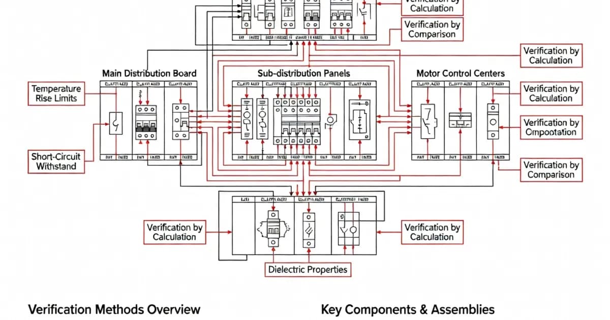
The standard recognizes three equivalent methods for design verification:
- Testing – verification through physical tests, typically used for representative assemblies and critical characteristics such as temperature rise, dielectric properties, and short-circuit withstand
- Calculation or measurement – used where accepted formulas or measurements can demonstrate compliance, especially for clearance distances and thermal assessment
- Application of constructive rules – design verification based on a previously tested reference design, provided the new configuration remains within the permitted boundaries
These methods give manufacturers flexibility, but not freedom to guess. The chosen route must be traceable, technically justified, and consistent with the clauses of IEC 61439-1. In practice, this means a panel builder may reuse verified design data only when the new build remains within the limits of the original verified arrangement.
Temperature Rise Verification
Temperature rise is one of the most important technical checks in the whole standard. Excess heat degrades insulation, accelerates component aging, affects protective device performance, and can create fire risk. Per IEC 61439-1 Clause 10.10, the assembly must be verified so that each circuit, and the assembly as a whole, can carry its rated current without exceeding permissible temperature limits.
Key requirements include the following:
- Verification must be performed at rated current with normal covers, partitions, and internal barriers in place
- Testing is typically conducted at an average ambient temperature not exceeding 35 °C
- Temperature-rise verification by calculation is limited in scope, including a maximum of 1600 A for certain multiple-compartment assemblies
- Group rated currents are used to focus thermal verification on loaded circuit groups rather than individual devices alone
As documented in Schneider Electric’s technical guidance, ambient conditions strongly influence thermal performance. A panel installed in an air-conditioned electrical room can often operate with different thermal margins than one installed in a hot industrial environment, but any adjustment must remain consistent with the rated conditions and the verified design basis.
From a design perspective, temperature-rise verification is not just about the total current entering the enclosure. It also depends on conductor routing, busbar cross-section, compartmentalization, internal ventilation, power losses of devices, and the number of simultaneously loaded outgoing circuits. For this reason, manufacturer documentation often provides power-loss tables and design verification workbooks to support compliant selection and assembly.
Short-Circuit Withstand Strength
IEC 61439 requires the assembly to withstand the thermal and mechanical effects of prospective short-circuit currents for the declared duration and protective arrangement. The busbar system, branches, supports, enclosures, and internal connections must all be evaluated as part of the overall assembly behavior.
A notable practical rule concerns non-protected live conductors. Where such conductors are installed in compliance with the standard, the total length between the main busbar and each associated supplementary circuit protective device should not exceed 3 meters. This limitation helps reduce exposure to fault energy and supports the coordination of conductors with protective devices.
The installer and panel builder must also ensure that conductor types and routing prevent phase-to-phase or phase-to-earth short circuits. Proper mechanical support, insulation, segregation, and coordination with SCPDs are essential to achieving the declared short-circuit withstand capability.
Electric Shock Protection Classification
IEC 61439-1:2020 introduces class-based assembly concepts for protection against electric shock. This is an important development because it helps align assembly design with modern insulation strategies and product labeling expectations.
Class I assemblies achieve protection through insulation of live parts and by connecting accessible metallic parts to the protective conductor system. These assemblies are identified by the protective conductor symbol.
Class II assemblies achieve protection through double insulation or reinforced insulation, and are identified by the double-square symbol. This concept is particularly relevant where the design intends to eliminate reliance on protective earthing for safety in the same way as Class I arrangements.
Verification of electric shock protection includes multiple checks, such as:
- IP XXB verification and insulating material checks
- Mechanical operation tests
- Dielectric property verification
- Resistance measurement between exposed conductive parts and the PE terminal
- Short-circuit strength verification of the protective circuit
IEC 60529 is referenced for ingress protection testing concepts, and the enclosure’s degree of protection must be suitable for the environment in which the assembly will be installed.
Conductor Installation Requirements
Conductor selection and installation are treated as essential safety functions, not as minor workshop details. Non-protected live conductors must be selected and routed to prevent dangerous short circuits. The standard gives normative requirements for conductor arrangements, and these requirements are intended to ensure repeatable performance under fault and service conditions.
For the panel builder, this means that conductor length, insulation rating, bending radius, support spacing, and proximity to metalwork all matter. In a compliant assembly, the internal wiring must be consistent with the tested or verified design, not just electrically adequate in a loose sense.
Significant Technical Changes in IEC 61439-1:2020
The 2020 edition of IEC 61439-1 introduced several important updates that affect design and verification practice. These revisions reflect the increasing complexity of modern low-voltage systems, including DC distribution, power conversion systems, and electronically controlled loads.
- Clarification on power conversion systems – power electronic converters, switch-mode power supplies, uninterruptible power supplies, and adjustable speed power drive systems are verified to their relevant product standards before incorporation into assemblies
- Group rated current concept – thermal verification now better reflects the actual loading of circuit groups within an assembly
- DC requirements – the standard now addresses direct current applications more explicitly
- Class I and Class II assemblies – a formal protection classification for electric shock safety
These changes are important because modern assemblies increasingly combine traditional AC distribution with electronics-heavy subsystems. A UPS, variable speed drive, or DC power section may generate different loss profiles, transient stresses, and installation constraints than conventional electromechanical feeders. IEC 61439-1:2020 makes the verification approach more capable of handling those realities.
Comparison of Verification Methods
| Verification Method | Typical Use | Advantages | Limitations |
|---|---|---|---|
| Testing | Temperature rise, dielectric properties, short-circuit strength, protection circuits | Direct evidence, widely accepted, strong technical confidence | Requires representative hardware, time, and laboratory resources |
| Calculation or Measurement | Clearance, thermal assessment, certain performance checks | Efficient for variant designs, supports engineering workflows | Limited by scope and assumptions; must match standard conditions |
| Constructive Rules | Variant assemblies based on a verified reference design | Fastest route for families of similar panels | Only valid within strict dimensional, construction, and loss limits |
In practical manufacturing, the best approach is usually a combination of all three methods. A manufacturer may test a reference assembly, calculate thermal margins for selected variants, and apply constructive rules for repeated configurations. The critical requirement is that each design decision remains within the verified envelope.
Related IEC and EN Standards
IEC 61439 does not exist in isolation. It interfaces with several other standards that define the components, enclosures, and test methods used in a complete assembly.
- IEC 60947 – low-voltage switchgear and controlgear component standards, including circuit breakers, disconnectors, contactors, and motor starters
- IEC 60529 – ingress protection code, referenced for enclosure protection and IP XXB-related testing concepts
- IEC 62271 – high-voltage switchgear and controlgear, relevant where the application extends beyond low-voltage scope
- DIN EN 60890 – widely used as a reference methodology for temperature rise verification and calculation practice
These standards work together. For example, a circuit breaker may comply with IEC 60947, but once it is installed into an assembly, the assembly must still meet IEC 61439 requirements for thermal behavior, clearances, conductor arrangement, and protection coordination.
Verification of Temperature Rises in Practice
Temperature-rise verification is often the most demanding aspect of compliance because it depends on the interaction of many variables. As noted in technical guidance from ABB and Schneider Electric, manufacturers usually document power losses, busbar data, and assembly configurations so that thermal calculations can be repeated and audited.
Clause 10.10 in IEC 61439-1 is the key reference for this work. In a typical compliant workflow, the engineer evaluates:
- Incoming current and group rated currents
- Busbar cross-section and material
- Device power losses at rated load
- Internal segregation and compartment layout
- Ventilation paths and enclosure heat dissipation
- Ambient temperature and installation conditions
For many panels, the thermal limit is not defined by the main incomer alone. Outgoing groups, densely packed control devices, contactors, and auxiliary power supplies may create localized hot spots. This is why the standard focuses on the entire assembly and not just individual products inside it.
Design Best Practices for IEC 61439 Compliance
A compliant design begins with a complete definition of operating conditions. The panel builder should determine rated current, prospective short-circuit current, ambient temperature, altitude if relevant, installation environment, segregation requirements, and any special service conditions before finalizing the layout.
Conductor Routing and Protection
Good conductor routing improves both safety and maintainability. Keep non-protected live conductors short, secure them mechanically, and route them away from sharp edges and metal supports. Maintain the standard’s 3-meter limit for specified non-protected conductor runs between the main busbar and associated SCPDs, and use insulation and segregation methods that prevent inadvertent phase contact.
Where possible, design busbar and cable routing to minimize thermal congestion. A clean internal layout with predictable air gaps and stable support points is easier to verify and more reliable in service.
Assembly Configuration
When using a verified reference design, do not exceed the validated limits for overall dimensions, internal separation changes, power losses, and outgoing circuit count. The research indicates that design-rule reuse is only acceptable when the new functional unit belongs to the same reference group and remains same or smaller in loss and same or larger in size as permitted by the constructive rules.
That means a “similar-looking” panel is not automatically a compliant variant. If the new design has more heat, less separation, or a different construction method, it may require fresh verification.
Environmental Considerations
IEC 61439 uses 35 °C average ambient temperature as the standard thermal reference for many tests. That does not mean every assembly must be installed in a 35 °C environment, but it does mean the declared performance must remain valid under the agreed service conditions. If the actual site is hotter, dustier, or more vibration-prone than the reference condition, the design may need derating or additional verification.
For installations in air-conditioned electrical rooms, engineers may be able to improve usable current capacity, but this must be done in a controlled and documented way, based on the verified design and site conditions.
Global Adoption and Harmonization
The IEC 61439 series has achieved broad international acceptance and is now the common reference point for low-voltage assembly compliance in many markets. This harmonization benefits engineering consultants, original equipment manufacturers, assembly manufacturers, test laboratories, distributors, and end users by reducing ambiguity and aligning expectations across the supply chain.
One of the most valuable consequences of this harmonization is the clearer division of responsibilities. The original manufacturer is responsible for the verified design, while the assembly manufacturer is responsible for ensuring the final build remains within the verified design envelope. This approach creates a more disciplined compliance process and helps prevent the misuse of mixed components or undocumented modifications.
As UL and other technical bodies note, the IEC 61439 framework is now the standard reference for modern low-voltage switchboards, panelboards, and control assemblies. The result is a more robust technical basis for procurement, specification, manufacturing, inspection, and acceptance testing.
Practical Implications for Panel Builders and Specifiers
For panel builders, IEC 61439 means that documentation is just as important as fabrication quality. A compliant assembly should be supported by design verification records, routine test records, thermal data, wiring details, device ratings, and a clear identification of the applicable standard part.
For specifiers and end users, the standard provides a better way to compare solutions. Instead of relying on vague claims of quality, they can ask whether the assembly has been verified for temperature rise, short-circuit withstand, dielectric performance, and protection against electric shock under the declared service conditions.
For consultants and system designers, IEC 61439 improves coordination between the electrical installation and the final assembly. It gives a structured basis for selecting incomers, feeders, segmentation, enclosure type, and device classes so that the panel can perform safely throughout its intended service life.
Summary
IEC 61439 is the foundational standard series for low-voltage panel assemblies. It provides a unified technical framework for design, verification, construction, and documentation. Its strongest contribution is the move from component-based assumptions to assembly-based verification. That shift forces the manufacturer to prove that the complete panel, not just the individual devices inside it, satisfies requirements for thermal performance, short-circuit strength, electric shock protection, and environmental resilience.
In modern electrical engineering,
Related Panel Types
Primary power distribution from transformer to sub-circuits. Rated up to 6300A. Houses main incoming breaker, bus-section, and outgoing feeders.
Centralized motor control with starters, contactors, overloads, and VFDs in standardized withdrawable/fixed functional units.
High-capacity power distribution for industrial facilities. Controls and distributes incoming power to MCC, APFC, and downstream loads.
Related Standards
Frequently Asked Questions
Ready to Engineer Your Next Panel?
Our team of electrical engineers is ready to design, build, and deliver your custom panel solution — fully compliant with international standards.