VFD Panel Design and Installation Best Practices
Engineering VFD panels for reliable motor speed control.
VFD Panel Design and Installation Best Practices
Variable Frequency Drive panels are engineered low-voltage assemblies that combine an AC drive with protection, isolation, filtering, cooling, and optional bypass functions in a single IEC 61439-compliant enclosure. In practical industrial use, these panels control motor speed and torque while also protecting the drive, motor, and surrounding installation from overload, short circuit, electromagnetic interference, and excessive heat. Per IEC 61439-1 and IEC 61439-2, the completed assembly must be verified as a whole, not as a collection of individually certified parts.
Typical VFD panels support motor ratings from 0.75 kW up to 500 kW at 400 V or 690 V, with busbar systems commonly rated 1,600 A, 3,200 A, or 4,000 A depending on duty, short-circuit level, and enclosure architecture. As documented in the Siemens and IEC 61439 design guidance, the panel builder is responsible for proving that the assembly meets the declared performance under real installation conditions, including temperature rise, dielectric strength, and short-circuit withstand capability.
What makes a VFD panel different from a standard motor control panel?
A conventional motor starter panel generally provides fixed-speed starting and stopping through contactors, overload relays, and protective devices. A VFD panel goes further by electronically varying motor frequency and voltage to control speed, reduce inrush current, improve process control, and lower energy consumption in variable-torque applications. Because the drive itself generates harmonic content, switching transients, and heat, VFD panels require more disciplined layout, filtering, segregation, and thermal design than a basic control panel.
In many installations, the VFD panel also includes a line reactor or DC choke, an EMC/RFI filter, an output reactor or dV/dt filter, bypass contactors, surge protection devices, control transformers, and dedicated cooling equipment. Each of these elements affects compliance and reliability. The completed assembly must therefore be treated as a coordinated system rather than a simple enclosure with a drive mounted inside.
Technical Specifications and IEC 61439 Compliance
IEC 61439 defines the rules for low-voltage switchgear and controlgear assemblies, including the general requirements in IEC 61439-1 and the specific requirements for power switchgear and controlgear assemblies in IEC 61439-2. For VFD panels, the key compliance issue is design verification. The manufacturer must demonstrate that the assembly meets the declared ratings for current, temperature rise, dielectric properties, and short-circuit performance.
Design verification under IEC 61439 can be achieved in three ways: testing under specific conditions, calculation based on defined rules and parameters, or comparison with a previously verified reference design. In all cases, the verification must cover the complete assembly. Component certificates alone do not prove that the finished panel is compliant.
For multi-compartment assemblies, the temperature-rise verification approach by calculation is generally limited to assemblies rated up to 1,600 A. Beyond that rating, physical testing is required. This is especially relevant in high-density VFD panels, where drive losses, busbar losses, and enclosure heat buildup can quickly exceed safe limits if the cooling strategy is not engineered properly.
Relevant standards for VFD panel design
| Standard | Scope | Relevance to VFD panels |
|---|---|---|
| IEC 61439-1 | General rules for low-voltage assemblies | Design verification, dielectric performance, temperature rise, clearances and creepage |
| IEC 61439-2 | Power switchgear and controlgear assemblies | Rules for distribution boards, MCCs, and PCC-style assemblies used with drives |
| IEC 60947 | Low-voltage switchgear and controlgear components | Specification of MCCBs, fuses, disconnectors, contactors, and overload devices |
| IEC 60947-2 | Automatic circuit breakers | Incoming protection and short-circuit interruption coordination |
| EN 61800-3 | EMC requirements for adjustable speed drives | Conducted and radiated emission control, filter selection, cable practice |
| IEC 60079 | Explosive atmospheres equipment | Applicable when the VFD panel is installed for hazardous-area service |
As noted in IEC 61439-based panel design guidance, short-circuit withstand strength is expressed through ratings such as Icw and Ipk, while insulation integrity is confirmed through dielectric verification. These are not optional design details; they are core safety outcomes that determine whether the panel can be accepted for service.
Forms of Separation and Internal Architecture
IEC 61439 defines Forms of Separation from Form 1 through Form 4, with sub-forms a and b for some arrangements. In VFD panel applications, Form 3b or Form 4b is often preferred because these forms allow the segregation of busbars, functional units, and terminals into dedicated compartments. This improves operator safety, fault containment, and maintenance access.
Form selection should follow the intended maintenance strategy. If the application requires work on adjacent live sections without shutting down the entire panel, stronger segregation is justified. Metallic partitions, insulated busbars, separate cable chambers, and IP-rated doors are all common methods of achieving this level of internal separation. The more critical the process, the more valuable compartmentalization becomes.
A well-structured VFD assembly usually separates the following zones:
- Incoming supply and main protection
- Drive power section
- Control and communication section
- Output and motor cable termination section
- Bypass or alternate feed section, if used
- Cooling and ventilation pathway
This layout supports maintainability and reduces the chance that a single fault will cascade across the entire panel. It also helps with electromagnetic segregation, which is essential when power conductors, control wiring, and encoder or communication cables are installed in the same enclosure.
Functional Components and Technical Architecture
Incoming protection and isolation
Every VFD panel should begin with a properly sized incoming isolator or disconnecting means and short-circuit protective devices such as an MCCB or fuse combination. Per IEC 60947-2, the incoming device must be selected for the available fault current, operating duty, and coordination with downstream components. The panel designer must also consider the drive manufacturer’s specified upstream protection, which may require particular fuse types or breaker curves to preserve drive integrity.
Incoming protection serves two purposes. First, it protects the assembly from external system faults. Second, it limits the energy delivered to internal faults so that the enclosure, busbars, and drive components remain within their short-circuit withstand limits.
Filtering and harmonic management
VFDs are a major source of electrical noise because their power electronics switch at high frequency. To control the resulting interference and voltage stress, the panel often includes line reactors, DC chokes, EMC filters, and output reactors. These components are selected based on cable length, motor type, installation environment, and compliance targets under EN 61800-3.
Input line reactors help limit inrush current and reduce harmonic distortion on the supply side. DC chokes improve the input current waveform in some drive architectures. EMC or RFI filters suppress conducted emissions and protect nearby instrumentation, PLCs, and communication networks. Output reactors and dV/dt filters reduce peak voltage at the motor terminals, which is especially important when motor cables are long or when the installation uses older motor insulation systems.
As documented in industrial drive design guides, output-side filtering becomes increasingly important as cable length increases. Without the proper filter, reflected wave effects can create damaging voltage spikes at the motor, shortening winding life and increasing nuisance trips.
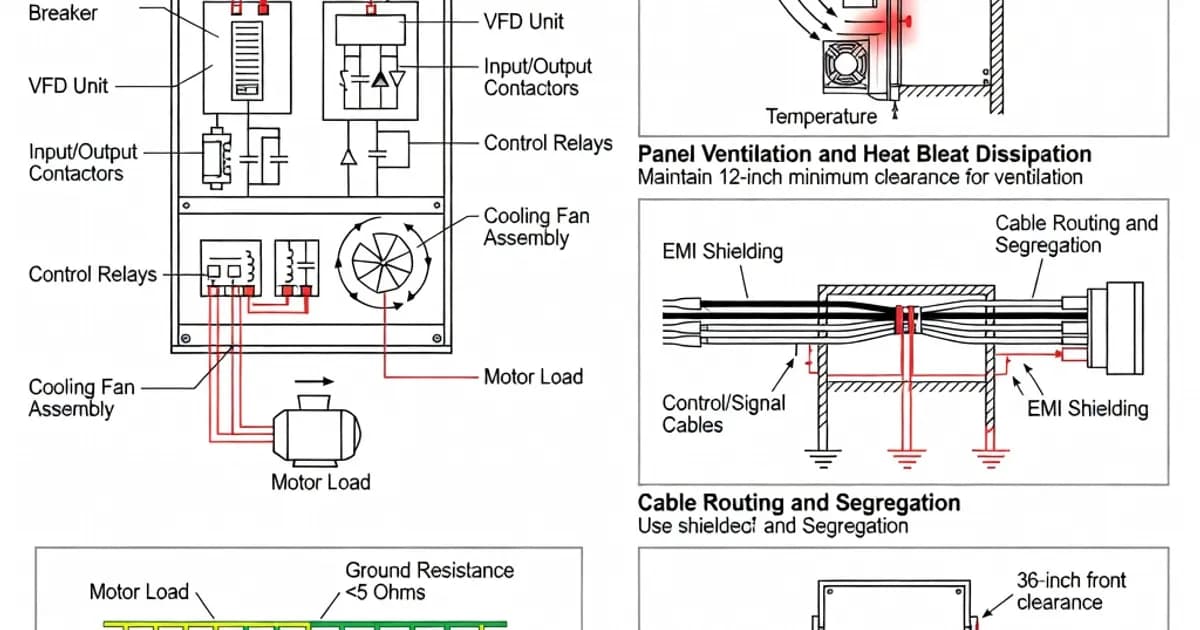
Thermal management
Heat is one of the primary limiting factors in VFD panel design. Drive losses are typically in the range of 2% to 4% of rated motor power, and that heat must be removed from the enclosure without overheating adjacent devices. If the panel is densely populated or installed in a hot plant room, passive ventilation is often insufficient.
Common thermal management strategies include filtered forced ventilation, heat exchangers, and liquid cooling for high-density applications. The correct approach depends on total heat dissipation, ambient temperature, enclosure size, and IP/NEMA requirements. In many projects, the thermal design must also account for derating at altitude or elevated ambient conditions. A panel that is safe at 25°C may not remain compliant at 45°C without redesign.
Thermal verification is not an afterthought. Under IEC 61439, the declared current rating must be supportable by the assembly under stated installation conditions. If the panel builder changes fan capacity, internal layout, cable routing, or component density, the original thermal verification may no longer be valid.
Bypass functionality
Critical processes often require a bypass arrangement so the motor can continue operating if the VFD is unavailable. Bypass may be manual or automatic, and may use contactors or a static transfer arrangement depending on the duty and recovery requirements. In a manual bypass scheme, the motor is transferred out of the drive path and connected directly to the line. In an automatic bypass scheme, the panel can recover operation with minimal interruption after a drive fault or maintenance event.
Bypass design must be coordinated carefully. The bypass path needs its own protective devices, interlocking, and indications to prevent simultaneous energization through conflicting paths. If the bypass circuit is poorly designed, it can create unsafe backfeed conditions or defeat the intended protection strategy.
Design Best Practices for Reliable and Compliant Panels
Size the panel from the load and fault level, not just the drive nameplate
The drive nameplate is only one input to the design process. A compliant VFD panel must be based on load current, starting profile, cable length, ambient temperature, short-circuit level, and duty cycle. The incoming busbar and protection devices must be selected for the available prospective fault current, while the enclosure and cooling arrangement must handle the worst-case heat load.
When multiple drives are installed in one panel, diversity and simultaneity should be assessed realistically. If all drives can run at full load at the same time, the thermal and electrical design must reflect that. Overestimating diversity can result in nuisance trips, reduced component life, or failure to pass design verification.
Keep power and control wiring physically separated
VFD installations are especially sensitive to poor cable segregation. High-frequency switching from the drive output can induce noise into control, sensor, and communication circuits. Best practice is to route power conductors in separate ducts or compartments from low-level control wiring, and to cross them only where necessary at right angles.
Encoder cables, analog signals, and fieldbus lines should be shielded and terminated according to the drive manufacturer’s instructions. Bonding of cable screens must be consistent and low impedance. Loose or high-resistance screen connections are a common source of EMC problems, intermittent faults, and unexplained process instability.
Coordinate components as a system
IEC 61439 places accountability on the assembly manufacturer to deliver a verified panel, but the assembly builder must also respect component manufacturer instructions. Drives, reactors, filters, contactors, and breakers each impose installation constraints. If the actual assembly ignores these requirements, the panel may be mechanically complete but technically noncompliant.
This is particularly important for clearances, ventilation spacing, torque values, and the placement of heat-sensitive devices. For example, placing an EMC filter immediately above a high-loss drive without a thermal barrier may violate the temperature-rise assumptions used during verification. Similarly, using a breaker with an unsuitable magnetic trip curve can create unwanted tripping during drive energization.
Document the design verification path
Every VFD panel should have a traceable verification file showing how compliance was established. That file should include the declared ratings, schematic, bill of materials, short-circuit calculations, thermal verification method, dielectric assumptions, protection coordination data, and routine test results. Per IEC 61439, design verification is not optional paperwork; it is evidence that the assembly is safe and fit for service.
Where the panel is based on a tested platform, the builder must document the reference design and any deviations. If the builder uses calculation rules, the assumptions must be explicit. This is essential for repeatability, handover, and future modifications.
Installation and Commissioning Best Practices
Prepare the installation environment
A VFD panel should be installed in a clean, dry, and well-ventilated location. Dust, moisture, corrosive fumes, and conductive contamination all reduce reliability. The ambient temperature should remain within the declared operating range, and there should be enough clearance for ventilation, maintenance access, and cable entry.
If the panel uses filtered forced ventilation, inlet and outlet paths must remain unobstructed. Filters must be maintainable without exposing personnel to live parts. In industrial environments with high dust loading, filter inspection intervals should be defined during commissioning rather than left to chance.
Verify grounding and bonding
Grounding and bonding are critical for safety and EMC performance. The panel enclosure, drive chassis, door bonds, cable gland plates, and cable shields must all be connected with low impedance. A poor earth path can increase touch voltage risk and exacerbate emissions problems. The earthing arrangement should follow the site’s protective conductor system and the equipment manufacturer’s instructions.
In addition, motor and drive cables should be terminated with correct gland hardware and shield termination practices. A mechanically secure but electrically weak shield termination is not acceptable in VFD service.
Test before energization
Before first energization, the panel should undergo routine tests appropriate to the assembly. These typically include visual inspection, checking of wiring and terminations, protection setting verification, insulation resistance checks where applicable, functional testing of interlocks, and confirmation of correct phase sequence and control logic. The panel should also be checked for mechanical integrity, fan rotation, filter placement, and torque on all power connections.
If the panel includes bypass functionality, the transfer sequence must be tested under controlled conditions. Any delay timers, permissives, or interlocks should be validated to ensure that the motor cannot be connected through conflicting paths.
Specification Comparison for Common VFD Panel Features
| Feature | Typical Specification | Design Benefit |
|---|---|---|
| Drive rating | 0.75 kW to 500 kW at 400 V or 690 V | Supports a wide range of industrial motor sizes |
| Busbar rating | 1,600 A, 3,200 A, or 4,000 A | Matches high-current distribution and multi-drive assemblies |
| Forms of separation | Form 3b or 4b | Improves safety, segregation, and maintenance access |
| Input protection | MCCB or fuses per IEC 60947-2 | Provides fault interruption and upstream coordination |
| EMC control | EN 61800-3 filters and shielded cabling | Reduces interference and improves process stability |
| Thermal management | Forced ventilation, heat exchanger, or liquid cooling | Controls drive losses and protects component life |
| Bypass option | Manual or automatic contactor bypass | Maintains operation during drive maintenance or faults |
Manufacturer Platforms and Panel Integration Examples
Major drive manufacturers provide platform-specific guidance that should be followed during panel design. Siemens commonly pairs SINAMICS G120 for standard-duty applications and S120 for more demanding servo or high-performance tasks, often within SIVACON, MNS, or Prisma-based panel architectures. ABB ACS880 drives are widely used in industrial low-voltage assemblies. Schneider Electric Altivar drives, Eaton and PowerXL drives, and LS Electric drive platforms are also commonly integrated into IEC 61439-compliant panels.
These platform-specific ecosystems matter because each drive family has its own preferred upstream protection, cooling orientation, EMC accessory set, and minimum clearance requirements. The panel builder must apply the manufacturer’s technical guide, not generic assumptions, when finalizing the design.
Common Mistakes to Avoid
- Using component ratings without verifying the complete assembly under IEC 61439.
- Ignoring drive losses and underestimating internal heat generation.
- Mixing power and control wiring in the same routing path.
- Omitting output reactors or dV/dt filters on long motor cable runs.
- Installing EMC filters without proper bonding and shield termination.
- Assuming bypass circuits are safe without interlock and transfer testing.
- Changing a verified design without rechecking thermal and short-circuit performance.
- Failing to document routine tests, protection settings, and design verification evidence.
Most field failures in VFD panels trace back to one of these issues: thermal overload, EMC noise, incorrect protection coordination, or poor segregation. Good design eliminates these problems before the panel reaches site
Related Panel Types
Related Components
Related Standards
Frequently Asked Questions
Ready to Engineer Your Next Panel?
Our team of electrical engineers is ready to design, build, and deliver your custom panel solution — fully compliant with international standards.