PLCs & I/O Modules in Motor Control Center (MCC)
PLCs & I/O Modules selection, integration, and best practices for Motor Control Center (MCC) assemblies compliant with IEC 61439.
Overview
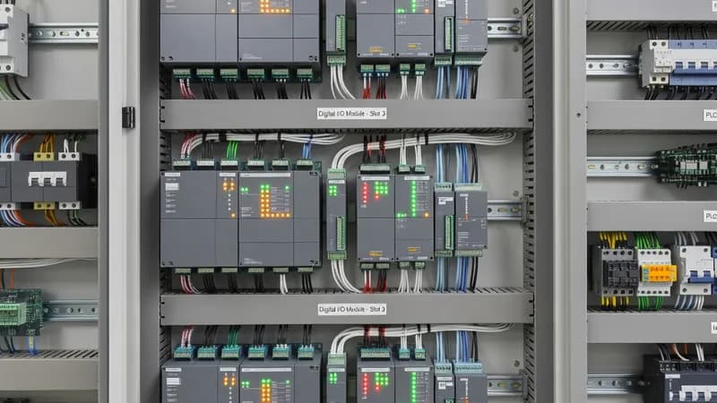
PLCs and I/O modules in a Motor Control Center (MCC) are selected to deliver sequencing, interlocking, diagnostics, and data acquisition for motor feeders without degrading the electrical performance or maintainability of the assembly. In an IEC 61439-1/2 MCC, the automation section is normally housed in a low-voltage control compartment or dedicated electronic bay, isolated from high-power sections containing ACB incomers, busbar chambers, MCCBs, contactors, overload relays, soft starters, and VFDs. Depending on the segregation philosophy, the MCC may be built with internal forms of separation such as Form 2b, Form 3b, or Form 4 to protect functional units, reduce arc propagation risk, and improve service continuity during maintenance. Component selection starts with the operating envelope. A PLC CPU, remote I/O slices, analog modules, and 24 VDC power supplies must be specified for the actual enclosure temperature, vibration level, electromagnetic environment, and humidity found inside an MCC lineup. Cabinets with multiple 250 A to 1600 A feeders, several 30 kW to 250 kW VFDs, or frequent motor starts can generate significant internal heat, so temperature-rise verification under IEC 61439-1 is essential. In many industrial projects, forced ventilation, filtered fan units, thermal partitioning, or a separate control cubicle is used to keep electronics within the allowable limits of the selected automation hardware. The automation architecture often combines hardwired motor control with industrial communications. PLCs can supervise direct-on-line starters, reversing starters, star-delta circuits, soft starters, and VFDs while exchanging data with protection relays, meters, and SCADA/BMS systems through PROFINET, Modbus TCP, EtherNet/IP, or Profibus. Typical I/O includes dry contacts for run/trip status, analog inputs for current, pressure, flow, or temperature signals, analog outputs for speed or setpoint control, and high-speed digital inputs for interlocks and encoder-related functions. For process-critical applications, redundant power supplies, remote I/O islands, and network redundancy are frequently adopted to improve availability. Coordination with IEC 60947 power devices is a key design requirement. The PLC logic must respect the trip curves and auxiliary signaling of MCCBs, motor protection relays, overloads, and ACBs so that fault handling is selective and restart logic is safe. In MCCs controlling pumps, compressors, conveyors, chillers, or process skids, the PLC is typically used for duty/standby rotation, automatic transfer between feeders, alarm escalation, and energy monitoring. For larger plants, communication-ready MCC sections support predictive maintenance by exposing motor starts, overload counts, drive fault codes, breaker status, and temperature alarms to the plant historian. Short-circuit withstand capability and dielectric performance must be verified at the assembly level, not only at the component level. Depending on the prospective fault current and upstream protective coordination, industrial MCCs are commonly designed for 25 kA, 50 kA, 65 kA, or 100 kA ratings. Where arc risk mitigation is required, IEC 61641 testing or an equivalent verified design approach may be specified for internal arc containment. If the MCC is installed in hazardous areas or near classified zones, enclosure selection and installation practices may also need to consider IEC 60079 requirements. EMC performance is especially important in VFD-heavy lineups, where shielding, segregation, grounding, and filter selection help prevent communication errors and false I/O signals. For EPC contractors, panel builders, and facility managers, a well-engineered PLC-and-I/O-equipped MCC provides a compact and maintainable automation platform that unifies motor control, diagnostics, and plant communications in one verified assembly. Patrion designs MCC solutions with clear segregation, labeled wiring, service access, spare terminal capacity, and expansion allowance so that future I/O additions, network upgrades, or drive integrations can be implemented without major reconstruction. The result is a standards-compliant, field-serviceable MCC that supports reliable operation, fast troubleshooting, and long-term plant digitalization.
Key Features
- PLCs & I/O Modules rated for Motor Control Center (MCC) operating conditions
- IEC 61439 compliant integration and coordination
- Thermal management within panel enclosure limits
- Communication-ready for SCADA/BMS integration
- Coordination with upstream and downstream protection devices
Specifications
| Property | Value |
|---|---|
| Panel Type | Motor Control Center (MCC) |
| Component | PLCs & I/O Modules |
| Standard | IEC 61439-2 |
| Integration | Type-tested coordination |
Other Components for Motor Control Center (MCC)
Branch protection 16A–1600A, thermal-magnetic or electronic trip
Motor speed control, energy savings, 0.37kW–500kW+
Reduced voltage motor starting, torque control, bypass options
DOL/star-delta/reversing starters, overload relays, Type 2 coordination
Overcurrent, earth fault, differential, generator protection relays
Copper/aluminum busbars, busbar supports, tap-off units
Other Panels Using PLCs & I/O Modules
Genset start/stop sequencing, synchronization, load sharing, and paralleling controls.
Process and machine control panels housing PLCs, I/O modules, relays, HMIs, and communication infrastructure.
Bespoke panel assemblies for non-standard requirements — special ratings, unusual form factors, multi-function combinations.
Frequently Asked Questions
Ready to Engineer Your Next Panel?
Our team of electrical engineers is ready to design, build, and deliver your custom panel solution — fully compliant with international standards.