Protection Relays in Motor Control Center (MCC)
Protection Relays selection, integration, and best practices for Motor Control Center (MCC) assemblies compliant with IEC 61439.
Overview
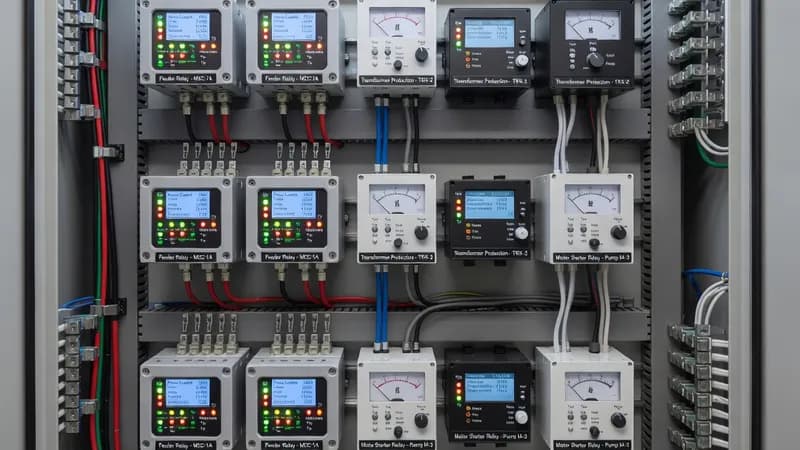
Protection relays in a Motor Control Center (MCC) are the intelligence layer that coordinates motor protection, feeder selectivity, and plant-wide diagnostics. In IEC 61439-2 assemblies, relays must be selected and integrated so their thermal load, wiring density, EMC behavior, and auxiliary supply requirements do not compromise the verified design of the enclosure. Typical MCC applications include DOL starters, star-delta starters, soft starter feeders, and VFD-controlled motor feeders serving pumps, fans, compressors, conveyors, and process drives. Depending on the application, relays may provide overcurrent, earth fault, phase loss, phase imbalance, thermal overload, locked rotor, stall, under/overvoltage, frequency, power, and directional or differential protection functions. For MCC engineering, relay selection starts with the feeder architecture. In a conventional feeder with an MCCB or fuse-switch disconnector, the relay must coordinate with upstream and downstream protective devices to achieve discrimination and minimize nuisance trips. Where motor protection is integrated with a contactor and overload relay, a multifunction protection relay may supervise the feeder and communicate alarms to SCADA/BMS over Modbus RTU, Modbus TCP, Profibus, Profinet, Ethernet/IP, or IEC 61850 gateways, depending on the plant standard. For VFD-fed motors, relay settings must account for inverter output characteristics, motor cable length, harmonic distortion, and any external dv/dt or sine filters. In soft starter applications, relay timing and current thresholds must be aligned with acceleration and bypass contactor logic. Thermal and electrical compatibility are critical inside MCC vertical sections and withdrawable or fixed modules. Protection relays should be rated for the ambient conditions declared for the assembly, commonly 35°C average with localized hot spots higher near busbar chambers, and must not reduce the panel’s verified current rating, whether 160 A, 250 A, 630 A, or higher feeder currents are used. The relay’s short-circuit withstand and associated CT secondary circuits must be coordinated with the MCC’s prospective short-circuit current, often 25 kA, 36 kA, 50 kA, or 65 kA for 1 s, as applicable to the design verification. Control wiring, terminal blocks, current transformers, and auxiliary power supplies must also be arranged to preserve creepage, clearance, and segregation requirements under IEC 61439 forms of separation, commonly Form 2, Form 3, or Form 4 depending on maintainability and touch protection needs. In hazardous or harsh industrial environments, the MCC may require additional considerations from IEC 60079 for explosive atmospheres and IEC 61641 for internal arc-fault mitigation, especially when relays are installed in densely packed intelligent MCC sections. Good practice includes separate control wire ducts, shielded communication cables, reliable DC or AC auxiliary supply, test plugs for CT circuits, event logging, self-diagnostics, and relay front-panel access without exposing live power parts. For motor-centric installations, integration with ACBs at incoming incomers, MCCBs or fused feeders, VFDs, soft starters, and protection relays creates a coordinated system that improves uptime, supports predictive maintenance, and simplifies fault tracing. Patrion designs and manufactures MCC panels in Turkey with IEC-aligned engineering, helping EPC contractors and industrial facilities implement robust relay-based protection schemes tailored to process criticality and space constraints.
Key Features
- Protection Relays rated for Motor Control Center (MCC) operating conditions
- IEC 61439 compliant integration and coordination
- Thermal management within panel enclosure limits
- Communication-ready for SCADA/BMS integration
- Coordination with upstream and downstream protection devices
Specifications
| Property | Value |
|---|---|
| Panel Type | Motor Control Center (MCC) |
| Component | Protection Relays |
| Standard | IEC 61439-2 |
| Integration | Type-tested coordination |
Other Components for Motor Control Center (MCC)
Branch protection 16A–1600A, thermal-magnetic or electronic trip
Motor speed control, energy savings, 0.37kW–500kW+
Reduced voltage motor starting, torque control, bypass options
DOL/star-delta/reversing starters, overload relays, Type 2 coordination
Copper/aluminum busbars, busbar supports, tap-off units
Programmable logic controllers, remote I/O, fieldbus communication
Other Panels Using Protection Relays
Primary power distribution from transformer to sub-circuits. Rated up to 6300A. Houses main incoming breaker, bus-section, and outgoing feeders.
High-capacity power distribution for industrial facilities. Controls and distributes incoming power to MCC, APFC, and downstream loads.
Automatic capacitor switching for reactive power compensation. Thyristor or contactor-switched, detuned or standard configurations.
Automatic changeover between mains and generator/UPS. Open or closed transition, with or without bypass.
Genset start/stop sequencing, synchronization, load sharing, and paralleling controls.
Process and machine control panels housing PLCs, I/O modules, relays, HMIs, and communication infrastructure.
Bespoke panel assemblies for non-standard requirements — special ratings, unusual form factors, multi-function combinations.
Enclosed soft starter assemblies for reduced voltage motor starting with torque control, ramp-up/down profiles, and bypass contactor options.
Active or passive harmonic filtering to mitigate THD from non-linear loads. Tuned LC filters, active filters, or hybrid configurations.
DC power distribution for battery systems, solar installations, telecom, and UPS applications. MCCB/fuse-based DC protection.
Fixed or automatic capacitor bank assemblies for bulk reactive power compensation in industrial and utility applications.
Frequently Asked Questions
Ready to Engineer Your Next Panel?
Our team of electrical engineers is ready to design, build, and deliver your custom panel solution — fully compliant with international standards.