Protection Relays in Main Distribution Board (MDB)
Protection Relays selection, integration, and best practices for Main Distribution Board (MDB) assemblies compliant with IEC 61439.
Overview
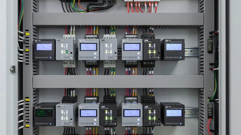
Protection relays in a Main Distribution Board (MDB) are the decision layer of the power distribution system, coordinating fault clearing, selective tripping, and event reporting across incomers, bus couplers, outgoing feeders, capacitor banks, transformers, generators, and critical process loads. In modern MDB assemblies built to IEC 61439-1 and IEC 61439-2, relay selection is not just about protection functionality; it must also align with the assembly’s rated current, temperature-rise limits, dielectric performance, short-circuit withstand capability, and form of internal separation. Depending on the architecture, relays may supervise ACBs on the main incomer, MCCBs on feeders, or communicate with intelligent trip units through Modbus, Profibus, Ethernet/IP, or IEC 61850 gateways for SCADA and BMS integration. Typical protection relay functions in an MDB include overcurrent, short-time, instantaneous, earth fault, restricted earth fault, under/overvoltage, under/overfrequency, phase unbalance, negative sequence, thermal overload, breaker failure, and synchrocheck for generator or utility tie applications. For transformer incomers and standby generation systems, numerical relays are often paired with ANSI/IEEE style functions translated into IEC 60255 logic, with coordination studies based on load profile, fault levels, and selectivity requirements. In higher-end MDBs, relays may manage dual-source incomers, automatic transfer logic, or bus section protection, ensuring continuity of supply to essential loads such as data centers, hospitals, water treatment plants, and industrial process lines. Selection criteria must consider the MDB’s prospective short-circuit current, typically verified at the assembly level against Icw, Ipk, and conditional short-circuit ratings. Relay inputs and auxiliary power supplies should be compatible with the control voltage architecture, commonly 24 V DC, 110 V DC, 110/230 V AC, or 220–240 V AC, depending on the project standard. Instrument transformer matching is critical: current transformers must be sized for accuracy class, burden, and saturation performance so the relay can detect faults correctly without nuisance tripping. For larger incomers, relays are frequently integrated with electronic trip units on ACBs rated from 1600 A to 6300 A, while feeder MCCBs may be coordinated through shunt trips, undervoltage releases, and digital protection modules. Inside the enclosure, thermal management is a major design factor. Protection relays, communication modules, and gateways generate heat and must be located to maintain panel temperature-rise compliance per IEC 61439-1/2. Space separation, wiring segregation, EMC control, and clean routing of CT/VT circuits help preserve measurement accuracy and reduce interference from VFDs, soft starters, and power factor correction equipment within the same MDB lineup. Where hazardous-area interfaces or special industrial environments apply, related equipment considerations may also reference IEC 60079 for explosive atmospheres and IEC 61641 for arc fault testing of low-voltage switchgear assemblies. A well-engineered protection relay scheme in an MDB improves uptime, maintains discrimination with downstream MCCB and MCB feeders, and supports predictive maintenance through event logs, disturbance records, and condition monitoring. Patrion’s engineering approach for MDB panels focuses on coordinated protection, verified short-circuit performance, and practical commissioning support for EPC contractors, panel builders, and facility operators.
Key Features
- Protection Relays rated for Main Distribution Board (MDB) operating conditions
- IEC 61439 compliant integration and coordination
- Thermal management within panel enclosure limits
- Communication-ready for SCADA/BMS integration
- Coordination with upstream and downstream protection devices
Specifications
| Property | Value |
|---|---|
| Panel Type | Main Distribution Board (MDB) |
| Component | Protection Relays |
| Standard | IEC 61439-2 |
| Integration | Type-tested coordination |
Other Components for Main Distribution Board (MDB)
Main incoming/outgoing protection, 630A–6300A, draw-out mounting
Branch protection 16A–1600A, thermal-magnetic or electronic trip
Copper/aluminum busbars, busbar supports, tap-off units
Energy meters, power quality analyzers, CT/VT, communication gateways
Type 1/2/3 surge arresters, coordination, monitoring
Other Panels Using Protection Relays
High-capacity power distribution for industrial facilities. Controls and distributes incoming power to MCC, APFC, and downstream loads.
Centralized motor control with starters, contactors, overloads, and VFDs in standardized withdrawable/fixed functional units.
Automatic capacitor switching for reactive power compensation. Thyristor or contactor-switched, detuned or standard configurations.
Automatic changeover between mains and generator/UPS. Open or closed transition, with or without bypass.
Genset start/stop sequencing, synchronization, load sharing, and paralleling controls.
Process and machine control panels housing PLCs, I/O modules, relays, HMIs, and communication infrastructure.
Bespoke panel assemblies for non-standard requirements — special ratings, unusual form factors, multi-function combinations.
Enclosed soft starter assemblies for reduced voltage motor starting with torque control, ramp-up/down profiles, and bypass contactor options.
Active or passive harmonic filtering to mitigate THD from non-linear loads. Tuned LC filters, active filters, or hybrid configurations.
DC power distribution for battery systems, solar installations, telecom, and UPS applications. MCCB/fuse-based DC protection.
Fixed or automatic capacitor bank assemblies for bulk reactive power compensation in industrial and utility applications.
Frequently Asked Questions
Ready to Engineer Your Next Panel?
Our team of electrical engineers is ready to design, build, and deliver your custom panel solution — fully compliant with international standards.