Capacitor Bank Panel for Commercial Buildings
Capacitor Bank Panel assemblies engineered for Commercial Buildings applications, addressing industry-specific requirements and compliance standards.
Overview
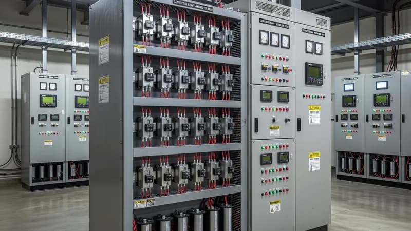
Capacitor Bank Panel assemblies for commercial buildings are engineered to improve power factor, reduce reactive energy charges, and stabilize busbar voltage in facilities with variable HVAC, elevator, lighting, and tenant-load profiles. Typical applications include shopping malls, office towers, hotels, hospitals, airports, and mixed-use developments where load diversity causes frequent power-factor swings and harmonic distortion. In these environments, the panel is usually integrated with the main distribution board (MDB), sub-main distribution boards, and building management system (BMS) to provide automatic power factor correction (APFC) with continuous monitoring of kvar demand, cos φ, voltage, current, and harmonic levels. A modern commercial-building capacitor bank panel is commonly built to IEC 61439-2 as a low-voltage switchgear and controlgear assembly, with component coordination under IEC 60947 series devices. Depending on site topology, fixed or automatic steps may be arranged using power factor controllers, capacitor contactors with pre-charge resistors, detuned reactors, discharge resistors, and step fuses or MCCBs for each stage. Typical installed ratings range from 50 kvar to more than 2000 kvar, with busbar and feeder current ratings from 160 A up to 3200 A or higher, selected according to the building’s maximum demand and future expansion margin. Short-circuit withstand levels are normally specified from 25 kA to 65 kA for 1 s, coordinated with upstream protection and prospective fault level at the MDB. Where commercial sites contain nonlinear loads such as VFDs, UPS systems, LED drivers, or escalator drives, detuned capacitor banks are preferred to prevent resonance and excessive capacitor stress. In these cases, reactor impedance is selected to shift the tuned frequency away from dominant harmonics, and thermal design must account for additional losses. Protection and switching may include MCCBs, MCBs, ACB incomers, protection relays, multifunction meters, surge protective devices, and ventilation fans with thermostat control. For critical facilities, step status, alarm outputs, and communication via Modbus RTU/TCP or BACnet are often interfaced to the BMS for remote supervision. Enclosure selection depends on the plantroom environment. Indoor panels are typically rated IP31 to IP54 with corrosion-resistant powder coating, while mechanical rooms with elevated dust or humidity may require higher ingress protection and forced ventilation. Form of separation is normally Form 2b, Form 3b, or Form 4 where safer maintenance segregation is needed. In commercial buildings located in hazardous or special locations such as fuel storage rooms or parking ventilation areas, additional consideration may be required for IEC 60079 zoning rules. If the panel is installed in a fire-compartment or emergency power environment, thermal endurance and cable entry arrangement must also be reviewed against IEC 61641 arc-containment considerations and local fire regulations. Patrion designs and manufactures capacitor bank panels for commercial buildings in Turkey for EPC contractors, consulting engineers, and facility owners requiring efficient reactive power compensation, compliant construction, and reliable lifecycle performance. Each assembly can be configured for manual, semi-automatic, or fully automatic operation, with step sizes tailored to the site load profile and utility penalties. Proper engineering of the panel, including capacitor duty rating, harmonic filtration, ventilation, and protection coordination, ensures stable operation, reduced electricity costs, and improved electrical system capacity across the building’s entire distribution network.
Key Features
- Capacitor Bank Panel configured for Commercial Buildings requirements
- Industry-specific environmental ratings and protections
- Compliance with sector-specific standards and regulations
- Optimized component selection for industry applications
- Integration with industry-standard control and monitoring systems
Specifications
| Property | Value |
|---|---|
| Panel Type | Capacitor Bank Panel |
| Industry | Commercial Buildings |
| Base Standard | IEC 61439-2 |
| Environment | Industry-specific ratings |
Other Panels for Commercial Buildings
Primary power distribution from transformer to sub-circuits. Rated up to 6300A. Houses main incoming breaker, bus-section, and outgoing feeders.
Final distribution for lighting and small power. MCB/RCBO-based with DALI or KNX integration options.
Automatic capacitor switching for reactive power compensation. Thyristor or contactor-switched, detuned or standard configurations.
Automatic changeover between mains and generator/UPS. Open or closed transition, with or without bypass.
Energy metering, power quality analysis, and multi-circuit monitoring with communication gateways.
Prefabricated busbar distribution per IEC 61439-6. Sandwich or air-insulated, aluminum or copper.
Bespoke panel assemblies for non-standard requirements — special ratings, unusual form factors, multi-function combinations.
Other Industries Using Capacitor Bank Panel
Frequently Asked Questions
Ready to Engineer Your Next Panel?
Our team of electrical engineers is ready to design, build, and deliver your custom panel solution — fully compliant with international standards.